duzenko
-
Posts
4149 -
Joined
-
Last visited
-
Days Won
50
Everything posted by duzenko
-
 Try the torrent magnet:?xt=urn:btih:740C47E25BC8BC472F7D2DC61FE746E685E2B99F
 -
Light frustums different in DR and TDM
duzenko replied to duzenko's topic in DarkRadiant Feedback and Development
Well, I kinda like some of the functionality the render matrix offers, like easy transformation of Vec3 to Vec4 -
Light frustums different in DR and TDM
duzenko replied to duzenko's topic in DarkRadiant Feedback and Development
Thanks I don't think we should not try to modify either of the two projection matrices, just pick one of them and use in both TDM and DR. Do you have any idea what they tried to achieve with this change and why? -
Light frustums different in DR and TDM
duzenko replied to duzenko's topic in DarkRadiant Feedback and Development
Once again, we need to decide if we want to switch back to the D3 matrix in TDM or switch to BFG matrix in DR I don't think I'm qualified to make that choice despite all the time I spent on this -
Light frustums different in DR and TDM
duzenko replied to duzenko's topic in DarkRadiant Feedback and Development
Did it ever go opensource like radiant? -
Light frustums different in DR and TDM
duzenko replied to duzenko's topic in DarkRadiant Feedback and Development
tr_lightRun.cpp in TDM R_DeriveLightData/R_ComputeSpotLightProjectionMatrix/R_SetLightProject Light.cpp in DR Light::updateProjection The math in D3 was okay, I suppose. The problem is that something changed in BFG and it's not consistent any more. The end point no longer projects to the far plane. I want to understand if it was a bug in BFG, or something changed in the logic behind the anchor points. And if it did change, then it should have been reflected in whatever editor they used for BFG maps? -
Light frustums different in DR and TDM
duzenko replied to duzenko's topic in DarkRadiant Feedback and Development
That's what I've been asking for a while but no one seems to care\know It seems asymmetric frustums have been the "norm" in D3/DR/TDM - of course projected lights in general were taken for granted and people just used them as is without any second thoughts If you create a projected light in DR and start dragging the anchor points around you're bound to lose symmetry soon enough Technically it would be easier to handle if left=right and up=down but there's an issue of compatibility. Expect some angry mappers when they find out their asymmetric lights have stopped working. It can also be used for optimization if the symmetric frustum spans too much. -
Light frustums different in DR and TDM
duzenko replied to duzenko's topic in DarkRadiant Feedback and Development
OTOH if we want to support "asymmetric" (off center) projections then would require exactly that - non-orthogonal basis? Like glm::frustum (btw maybe just use that?) -
Light frustums different in DR and TDM
duzenko replied to duzenko's topic in DarkRadiant Feedback and Development
In this case logically the resulting frustum center point is not what DR shows I would suggest to fix this in DR then -
Light frustums different in DR and TDM
duzenko replied to duzenko's topic in DarkRadiant Feedback and Development
Could you maybe shed some light why target, right, up aren't orthogonal? One difference between d3 and bfg is that BFG uses the target vector from spawnargs for Z basis vector and D3 computes a normal between up and right instead.
-
Light frustums different in DR and TDM
duzenko replied to duzenko's topic in DarkRadiant Feedback and Development
Forget about shaders, this is not about that No, the game, same as DR, uses the falloff texture. The texture decides where the light is brighter or dimmer. There's no shader math for that. The texture does not have to be symmetric, if a particular texture is symmetric, that still does not mean anything. There's no really need or sense to change anything in that regard. -
Light frustums different in DR and TDM
duzenko replied to duzenko's topic in DarkRadiant Feedback and Development
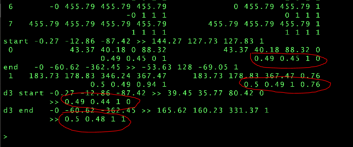
Added the test code for that (placed in the end of R_DeriveLightData) Results Unless I'm not mistaking it means that the BFG matrix does not map the end pos from the spawn args to light frustum "far" plane, unlike the D3 code At this point we should decide if it was a bug or a feature and what their intention was when they changed the matrix.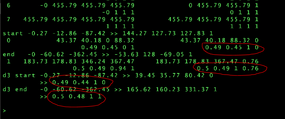
-
Light frustums different in DR and TDM
duzenko replied to duzenko's topic in DarkRadiant Feedback and Development
@stgatilovThanks for looking into this I think I got sidetracked and distracted you from the real problem Yes, the thing I wrote about in the last post is a non-issue. Since the baseLightProject is always based on the lightProject, they'll both produce the same result My problem is the code that builds lightProject. R_SetLightProject vs R_ComputeSpotLightProjectionMatrix will give different matrix sets and different frustums I'm going to try another thing now. Transform local start/end coordinates (in the spawn args) to global space and see where their "projections" are EDIT. Also note, that locally I reverted to return 1.0f / ( zNear + zFar ); in the end of R_ComputeSpotLightProjectionMatrix but did not commit to svn as I'm still investigation this -
Is the outline supposed to work for both old and new backend? I think it should though I vaguely remember something only working in new backend
-
Light frustums different in DR and TDM
duzenko replied to duzenko's topic in DarkRadiant Feedback and Development
Do we have a tutorial or video about managing projected lights in DR? E.g. I have no idea how to control it's parameters other than manually type into spawnargs -
Light frustums different in DR and TDM
duzenko replied to duzenko's topic in DarkRadiant Feedback and Development
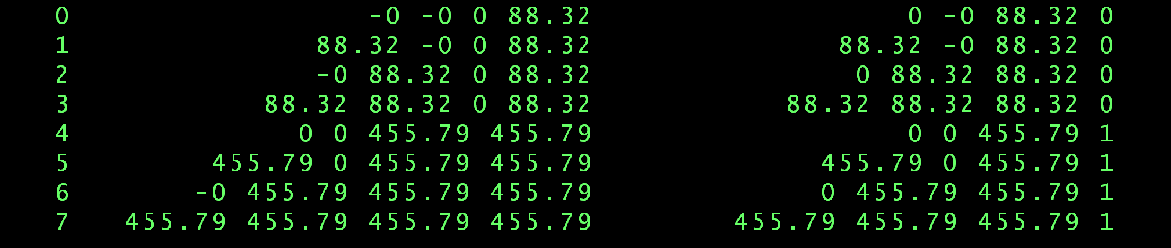
After some more investigation it seems that BFG projection matrix is different because it gives different transformation projection divider goes into W instead of Z falloff texture coordinate is not normalized This is produced by debug code in the end of R_DeriveLightData auto test = [light](idVec3 vert, int i) { idVec4 v4; light->baseLightProject.TransformPoint( vert, v4 ); auto& M2 = *(idMat4*) light->lightProject; idVec4 tmp( 0, 0, 0, 1 ); tmp.ToVec3() = vert; auto x = M2 * tmp; common->Printf( "%2d%30s%30s\n ", i, v4.ToString(), x.ToString() ); /*for ( int j = 0; j < 6; j++ ) { auto d = light->frustum[j].Distance( vert ); common->Printf( "%.1e ", d ); } common->Printf( "\n" );*/ }; for ( int i = 0; i < light->frustumTris->numIndexes; i++ ) { auto index = light->frustumTris->indexes[i]; auto vert = light->frustumTris->verts[index]; test( vert.xyz, i ); } ALIGNTYPE16 frustumCorners_t corners; idRenderMatrix::GetFrustumCorners( corners, light->inverseBaseLightProject, bounds_zeroOneCube ); for ( int i = 0; i < 8; i++ ) { test( idVec3( corners.x[i], corners.y[i], corners.z[i] ), i ); } Strangely here both frustumTris and frustumCorners_t map to texture space corners...
-
Light frustums different in DR and TDM
duzenko replied to duzenko's topic in DarkRadiant Feedback and Development
@stgatilov apparently the BFG code we switched to last year produces a different result compared to the old code It's R_SetLightProject vs R_ComputeSpotLightProjectionMatrix The old R_SetLightProject was inline with DR I'm not sure about why they changed it, maybe it makes more sense, but we need to maintain compatibility so revert that? -
Light frustums different in DR and TDM
duzenko replied to duzenko's topic in DarkRadiant Feedback and Development
Can anyone please explain what the start, target, end, up, right points for lights are defining? I mean, I can understand what they're defining, but how they're supposed to map to the projection matrix? Compare, for example const float targetDistSqr = light->parms.target.LengthSqr(); const float invTargetDist = idMath::InvSqrt(targetDistSqr); const float targetDist = invTargetDist * targetDistSqr; const idVec3 normalizedRight = light->parms.right * (0.5f * targetDist / light->parms.right.LengthSqr()); localProject[0][0] = normalizedRight[0]; localProject[0][1] = normalizedRight[1]; localProject[0][2] = normalizedRight[2]; localProject[0][3] = 0.0f; and auto rLen = _lightRightTransformed.getLength(); Vector3 right = _lightRightTransformed / rLen; Vector3 normal = up.cross(right).getNormalised(); auto dist = _lightTargetTransformed.dot(normal); if ( dist < 0 ) { dist = -dist; normal = -normal; } right *= ( 0.5 * dist ) / rLen; lightProject[0] = Plane3(right, 0); This already gives different results -
Light frustums different in DR and TDM
duzenko replied to duzenko's topic in DarkRadiant Feedback and Development
Next step is to compare DR's Light::updateProjection() and TDM's R_DeriveLightData -
Light frustums different in DR and TDM
duzenko replied to duzenko's topic in DarkRadiant Feedback and Development
I can see that DR does it corners in local space using plane intersections While TDM relies mostly on projection matrices But already the initial setup in R_DeriveLightData is wrong when it comes to building frustum planes -
Light frustums different in DR and TDM
duzenko replied to duzenko's topic in DarkRadiant Feedback and Development
It does not produce the actual corner coordinates though, does it? -
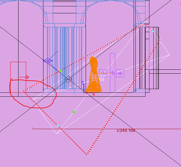
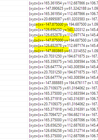
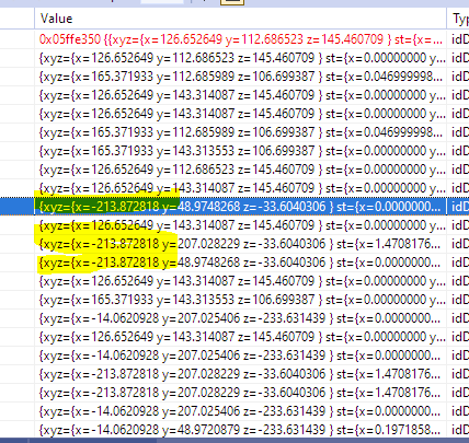
Not sure if it's a bug in DR or (most likely) TDM but I've been hit with this issue where a light ends up having different frustum vertices in TDM than it was set up in DR Map attached. Look at light_1 Its "far" corners seems to have the X coordianate of -125 When the light loads in TDM, the frustum corners can be rebuilt using different methods: R_PolytopeSurface gives -147 idRenderMatrix::GetFrustumCorners gives -213 This really messes up my volumetric shader Which one is supposed to be correct? idRenderMatrix::GetFrustumCorners is much farther from DR but R_PolytopeSurface's output is not even air-tight @stgatilov? @greebo Where can I find the code that calculates frustum vertices in DR? Maybe I should just copy-paste it in TDM and relax. volumetric.map duzenko.mtr
-
Could be low on RAM - maybe round down textures and try a small mission? Or could be 64-bit color compatibility - try to disable that There's a way to bypass vendor check and force install intel drivers, I did that on my Atom tablet many years ago. Search for steps.
-
No, it was from the old volumetric branch I'm trying to revive today But we staill do have a render function that always tries to draw client arrays
-
Some wisdom from debug profile logs