Search the Community
Showing results for tags 'modeling'.
-
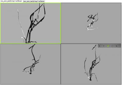
Hi, I thought I should document this discussion here, for future reference, as info on this subject has become quite scattered and out of date. I've been wrestling with MD5s for a while now with no success. Importing works but the meshes and armatures are problematic. I decided to start with an animated model from scratch. Followed a few instructions in videos or tutorials (most recently trying out Sotha's solution http://forums.thedarkmod.com/topic/14970-blender-rig-for-standard-male-npc/?do=findComment&comment=325423 ) but have yet to be able to export successfully. The animation oddly enough is working correctly (on the model viewer, havent gotten into the game yet), but the mesh itself is getting horribly deformed. Im using the io_scene_md5 importer/exporter. Going back to version 2.72 didnt solve it for me. In blender After exporting Any thoughts?
-
Hi! I am new here. I want to help with modeling. I would like to model a statue. When it's ok, I would like to model something like this or this. I use Blender and have already some experience with modeling. If you are interested, here are my prvious working examples: myportfolio nice greetings
-
Hi there! Since modular meshes are a thing in TDM, and I already saw some general misconceptions in the forums on how to make them, I thought I should show you one of basic techniques to make proper modular meshes, especially if you want to release them for others to use. First off, if you're new to the concept, have some preliminary reading: https://docs.unrealengine.com/udk/Three/rsrc/Three/ModularLevelDesign/ModularLevelDesign.pdf The document is old, but the principles of modular design stay the same. It's always about building the game world as fast as possible, while trying to save on polygons, textures and resources in general, and making the environment look as unique as you can. These seem like polar opposites at first, but with creative use of modular meshes you will reach that middle ground. Now, I'm not going to discuss my modeling techniques in much detail, since that's whole other topic, but we will stick to some ground rules: 1. Your wireframe has to be clean. I know this is modeling 101, but you can never stress enough how important it is. Essentially, your low-poly model has to be made with polygons (squares or rectangles) which can be divided into triangles when you convert it to a mesh. So, any piece rectangular flat surface should be divisible into 2 triangles. That doesn't mean you can't have triangles in your model. You can, they just won't be divided further. This is very simple mesh with 3 rectangular surfaces, in other words, it has 3 polygons. And this is how it should look like after export to mesh and in your game editor. As you see, everything is fine, there are 6 triangles. Now, in TDM module library I often see something like this: This is not a clean wireframe. You're looking at 14 triangles instead of 6. That's 42 edges instead of 18. While it may not be game-breaking now, it's definitely a waste of triangles. If you're going to have a whole collection of meshes built this way, you may be wasting processing power and lowering the overall game performance. Engines using lightmaps would probably have shadowing problems with this kind of wireframe. And that's how we move to rule number two, which is: 2. Save polygons whenever you can. Get rid of the faces players will never see. Use geometry only to convey believable shape of a model. Use high -> low poly model workflow and texture baking process to imitate complicated geometry with diffuse and normal textures. You don't need a thousand-polygon wall module, if you can fake it with normalmap and little visual difference. This is not only helpful in terms of performance, but it saves a lot of time at the model UVW Unwrap stage (it's easier / faster with fewer polygons to deal with). It also can be a design decision: whether it's a distant / skybox art or closer to the player, etc., etc. Now the rule number three, which is probably the most important of them all: 3. The pivot has to be moved to a place that allows most flexible use of a model, in as many scenarios as possible, and with grid set to as high number as possible. While this is not obligatory for unique objects, decorations and clutter, architectural meshes have to be cloned, moved, rotated and snapped to grid, as fast as you can. Typically, this depends on mesh dimensions and pivot placement. Since this all may sound very technical and abstract, let's get down to proper example. For my mission, I needed a wooden wall panel, something in the Builder's cathedral aesthetics. While browsing through many references, I found something appealing to my taste, but way above my modeling skills: I was also taking screenshots of Dishonored. I liked the Overseers' HQ, and I wanted to have something similar in terms of modularity: Notice that you don't need any special columns for outward corners, or to break up panels that are next to each other. I thought that the easiest way to achieve something similar would be to have a horizontal tiling texture with sections. Since I'm using 2048 textures as a base, I knew that 128 x 256 units will be enough for a wall panel, and I'll be able to divide it properly later. I didn't want the low-poly mesh to be complex, so I thought all I need is an upper trim section, the main section with inset panels, and the ground trim section. Technically, I could probably use one trim section and overlapping UVs to save on texture space, but I thought that is a bit too far Besides, any dirt layer on that would have the same spots or scratches on both trims, and that might look weird. This was the initial basic outline of my low-poly mesh. I thought the trim parts will be 16 u high, to fit better with overall proportions. Besides, if I'd changed my mind and decided that it's better to scale the model down to 64 x 128 u, it would have looked good as well. Now, since my drawing skills are basically none, I decided to model parts and decoration that would end up as baked texture and normal. I started with the middle section. Since the panel would be 256 u long, it was easy to divide it into 8 sections, 32 u each. I added thin strips between each section to make things a bit more interesting. Notice that I cut the strip by half on each end to make it tile properly later. I made a few adjustments and started adding decoration for the insets: Since there aren't many Builder insignia concept artworks, I tried making something on my own. It's kind of too close to hammerite stuff, but I liked it enough to leave it that way. Now the trims. Actually, one trim for the ground that is reversed for the upper section: The final model wasn't even high poly, medium poly at best. You're looking at 5200 polygons. I unwrapped the initial low-poly mesh (well, a plane with 3 setions), so it was super easy to bake the medium poly mesh onto it. I was using only half of the 2048 texture space. I could crop the texture to 1024 x 2048 and reposition UVs, but I decided that later I'd make a column, or another variation of this panel, so this space would not go to waste. This was kind of crucial moment and time when fun began. First thing I did was to check the pivot. I aligned it with the plane, moved it to the left side, and placed it on the ground. This way the model would be much easier to manipulate, whether it's moving around, rotating, or snapping to brushes or other meshes. Then I had to determine the final shape of the mesh and its possible uses. I applied the baked AO as bitmap to see whether the texture tiles (it did), and decided to tilt trim sections a bit, so it reflects the shape of medium poly mesh a bit more. I knew that players wouldn't see the bottom part of the mesh, but I wasn't so sure about the upper part. I decided to make the upper finish and used the trim part of the texture for it. Then I built a few walls to see how the mesh would look placed against them. That was when I realized my mistake. The pivot was in line with the middle section now, so, when I snapped it to a wall, the middle section was z-fighting with a wall. Duh! I selected the polygon and moved it 1 unit to the front. When I made sure that I can safely snap the mesh to walls and its clones, I proceeded to divide it to parts. As you see, this is still 128 x 256 wall panel, it's not really flexible. We need different length variations. Since I divided the medium poly into 8 even sections, I could slice the low poly mesh into chunks. Since having 8 different parts isn't that useful in the long run, I decided to clone the mesh, cut off one panel, clone the result cut another panel, etc. This way I came up with panels that are 224, 192, 160, 128, 96, 64 and 32 units long, respectively: The question is: do you really need that many panel variations? Typically, no. Four should be more than enough. You can always have a panel going through a wall, where player will never see it, so you don't need to be that precise and have all the length variants. Still, there was one thing even more important: corner pieces. I cloned the two-inset (64-unit) version of the panel to cut it in half. Then I rotated the "right half" 90° to the left to see the result. It was far from satisfactory. I knew that I'd need to align the upper and lower trims to form the corner, but I completely forgot that moving the middle section 1 unit to the front (to avoid z-fighting with walls) would create half a unit gap in the corner. This is how it looked after I aligned the vertices: This is where I could go to making textures and testing meshes in the editor, but there's also a problem of having inward corners. Many developers don't even bother with these, there will be some z-fighting of the upper part, in the small corner where meshes intersect. Not a big deal, but you can have such corners if you want as well. I felt like I had complete package, so I made some preliminary textures and material, then I begun exporting all pieces in .ASE format. All in all, I managed to create 12 variants of one mesh to cover the whole variety of its uses. After a few iterations of _d, _s, and _n textures, I came up with something like this: Edit: after getting some feedback I reworked the trims to give them more depth and proper silhouette, so the final result looks like this: This also demonstrates how important it is to bounce your ideas off someone or to show your work for peer review. A fresh look and healthy criticism can have very positive impact on quality of your work. I hope you'll find this useful while designing your own modular parts, let me know if you have any questions.


