Search the Community
Showing results for tags 'lighting'.
Found 7 results
-
Hello, everyone! In this multi-part, comprehensive tutorial I will introduce you to a new light type that has been available in The Dark Mod since version 2.06, what it does, why you would want to use it and how to implement it in your Fan Missions. This tutorial is aimed at the intermediate mapper. Explanations of how to use DarkRadiant, write material files, etc. are outside of its scope. I will, however, aim to be thorough and explain the relevant concepts comprehensively. Let us begin by delineating the sections of the tutorial: Part 1 will walk you through four, distinct ways to add ambient light to a scene, the last way using irradiance environment maps (or IEMs). Lighting a scene with an IEM is considered image-based lighting. Explaining this concept is not in the scope of this tutorial; rather, we will compare and contrast our currently available methods with this new one. If you already understand the benefits IBL confers, you may consider this introductory section superfluous. Part 2 will review the current state of cubemap lights in TDM, brief you on capturing an environment cubemap inside TDM and note limitations you may run into. Three cubemap filtering applications will be introduced and reviewed. Part 3 will go into further detail of the types of inputs and outputs required by each program and give a walkthrough of the simplest way to get an irradiance map working in-game. Part 4 will guide you through two additional, different workflows of how to convert your cubemap to an irradiance map and unstitch it back to the six separate image files that the engine needs. Part 5 will conclude the tutorial with some considerations as to the scalability of the methods hitherto explained and will enumerate some good practices in creating IEMs. Typical scenes will be considered. Essential links and resources will be posted here and a succinct list of the steps and tools needed for each workflow will be summarized, for quick reference. Without further ado, let us begin. Part 1 Imagine the scene. You’ve just made a great environment for your map, you’ve got your geometry exactly how you want it… but there’s a problem. Nobody can appreciate your efforts if they can’t see anything! [Fig. 1] This will be the test scene for the rest of our tutorial — I would tell you to “get acquainted with it” but it’s rather hard to, at the moment. The Dark Mod is a game where the interplay between light and shadow is of great importance. Placing lights is designing gameplay. In this example scene, a corridor with two windows, I have decided to place 3 lights for the player to stealth his way around. Two lights from the windows streak down across the floor and a third, placeholder light for a fixture later to be added, is shining behind me, at one end of the corridor. Strictly speaking, this is sufficient for gameplay in my case. It is plainly obvious, however, that the scene looks bad, incomplete. “Gameplay” lights aside, the rest of the environment is pitch black. This is undesirable for two reasons. It looks wrong. In real life, lights bounce off surfaces and diffuse in all directions. This diffused, omni-directional lighting is called ambient lighting and its emitment can be termed irradiance. You may contrast this with directional lighting radiating from a point, which is called point lighting and its emitment — radiance. One can argue that ambient lighting sells the realism of a scene. Be that as it may, suppose we disregard scary, real-life optics and set concerns of “realism” aside… It’s bad gameplay. Being in darkness is a positive for the player avatar, but looking at darkness is a negative for the player, themselves. They need to differentiate obstacles and objects in the environment to move their avatar. Our current light level makes the scene illegible. The eye strain involved in reading the environment in these light conditions may well give your player a headache, figurative and literal, and greatly distract them from enjoying your level. This tutorial assumes you use DarkRadiant or are at least aware of idtech4’s light types. From my earlier explanation, you can see the parallels between the real life point/ambient light dichotomy and the aptly named “point” and “ambient” light types that you can use in the editor. For further review, you can consult our wiki. Seeing as how there is a danger in confusing the terms here, I will hereafter refer to real life ambient light as “irradiant light”, to differentiate it from the TDM ambient lights, which are our engine’s practical implementation of the optical phenomenon. A similar distinction between “radiant light” and point lights will be made for the same reason. Back to our problem. Knowing, now, that most all your scenes should have irradiant light in addition to radiant light, let’s try (and fail, instructionally) to fix up our gloomy corridor. [Fig. 2] The easiest and ugliest solution: ambient lights. Atdm:ambient_world is a game entity that is basically an ambient light with no falloff, modifiable by the location system. One of the first things we all do when starting a new map is putting an ambient_world in it. In the above image, the darkness problem is solved by raising the ambient light level using ambient_world (or via an info_location entity). Practically every Dark Mod mission solves its darkness problem1 like this. Entirely relying on the global ambient light, however, is far from ideal and I argue that it solves neither of our two, aforementioned problems. Ambient_world provides irradiant light and you may further modulate its color and brightness per location. However, said color and brightness are constant across the entire scene. This is neither realistic, nor does it reduce eye strain. It only makes the scene marginally more legible. Let’s abandon this uniform lighting approach and try a different solution that’s more scene-specific. [Fig. 3] Non-uniform, but has unintended consequences. Our global ambient now down to a negligible level, the next logical approach would be hand-placed ambient lights with falloff, like ambient_biground. Two are placed here, supplementing our window point lights. Combining ambient and point lights may not be standard TDM practice, but multiple idtech4 tutorials extol the virtues of this method. I, myself, have used it in King of Diamonds. For instance, in the Parkins residence, the red room with the fireplace has ambient lights coupled to both the electric light and the fire flame. They color the shadows and enrich the scene, and they get toggled alongside their parent (point) lights, whenever they change state (extinguished/relit). This is markedly better than before, but to be honest anything is, and you may notice some unintended side-effects. The AI I’ve placed in the middle of the ambient light’s volume gets omnidirectionally illuminated far more than any of the walls, by virtue of how light projection in the engine works. Moving the ambient lights’ centers closer to the windows would alleviate this, but would introduce another issue — the wall would get lit on the other side as well. Ambient lights don’t cast shadows, meaning they go through walls. You could solve this by creating custom ambient light projection textures, but at this point we are three ad hocs in and this is getting needlessly complicated. I concede that this method has limited use cases but illuminating big spaces that AI can move through, like our corridor, isn’t one of them. Let’s move on. [Fig. 4] More directional, but looks off. I have personally been using this method in my WIP maps a lot. For development (vs. release), I even recommend it. A point light instead of an ambient light is used here. The texture is either “biground1” or “defaultpointlight” (the latter here). The light does not cast shadows, and its light origin is set at one side of the corridor, illuminating it at an angle. This solves the problem of omnidirectional illumination for props or AI in the middle of the light volume, you can now see that the AI is lit from the back rather than from all sides. In addition, the point light provides that which the ambient one cannot, namely specular and normal interaction, two very important features that help our players read the environment better. This is about as good as you can get but there are still some niggling problems. The scene still looks too monochromatic and dark. From experience, I can tell you that this method looks good in certain scenes, but this is clearly not one of them. Sure, we can use two, non-shadowcasting point lights instead of one, aligned to our windows like in the previous example, we can even artfully combine local and global ambient lights to furnish the scene further, but by this point we will have multiple light entities placed, which is unwieldy to work with and possibly detrimental to performance. Another problem is that a point light’s movable light origin helps combat ambient omnidirectionality, but its projection texture still illuminates things the strongest in the middle of its volume. I have made multiple experiments with editing the Z-projection falloff texture of these lights and the results have all left me unsatisfied. It just does not look right. A final, more intellectual criticism against this method is that this does not, in a technical sense, supply irradiant light. Nothing here is diffuse, this is just radiant light pretending the best it can. [Fig. 5] The irradiance map method provides the best looking solution to imbuing your scene with an ambient glow. This is the corridor lit with irradiance map lights, a new lighting method introduced in The Dark Mod 2.06. Note the subtle gradients on the left wall and the bounced, orange light on the right column. Note the agreeable light on the AI. Comparing the previous methods and this, it is plainly obvious that an irradiance environment map looks the most realistic and defines the environment far better than any of the other solutions. Why exactly does this image look better than the others? You can inform yourself on image-based lighting and the nature of diffuse irradiance, but images speak louder than words. As you can see, the fact of the matter is that the effect, subtle as it may be, substantially improves the realism of the scene, at least compared to the methods previously available to us. Procuring irradiance environment maps for use in lighting your level will hereafter be the chief subject of this tutorial. The next part will review environment cubemap capture in TDM, the makeIrradiance keyword and three external applications that you can use to convert a TDM cubemap into an irradiance map. 1 “ Note that the color buffer is cleared to black: Doom3 world is naturally pitch black since there is no "ambient" light: In order to be visible a surface/polygon must interact. with a light. This explains why Doom3 was so dark ! “ [source] Part 2 Cubemaps are not new to The Dark Mod. The skybox materials in some of our prefabs are cubemaps, some glass and polished tile materials use cubemaps to fake reflections for cheap. Cubemap lights, however, are comparatively new. The wiki page linked earlier describes these two, new light types that were added in TDM 2.05. cubicLight is a shadow-casting light with true spherical falloff. An example of such a light can be found in the core files, “lights/cubic/tdm_lampshade_cubic”. ambientCubicLight is the light type we will be focusing on. Prior to TDM 2.06, it acted as a movable, on-demand reflection dispenser, making surfaces in its radius reflect a pre-set cubemap, much like glass. After 2.06, the old behavior was discarded and ambientCubicLight was converted to accept industry standard irradiance environment maps. Irradiance environment maps (IEMs) are what we want to make, so perhaps the first thing to make clear is that they aren’t really “handmade”. An IEM is the output of a filtering process (convolution) which requires an input in the form of a regular environment cubemap. In other words, if we want to make an IEM, we need a regular cubemap, ideally one depicting our environment — in this case, the corridor. I say a snapshot of the environment is ideal for lighting it because this emulates how irradiant light in the real world works. All radiating surfaces are recorded in our cubemap, our ambient optic array as it were, then blurred, or convoluted, to approximate light scatter and diffusion, then the in-game light “shines” this approximation of irradiant light back to the surfaces. There is a bit of a “chicken and the egg” situation here, if your scene is dark to begin with, wouldn’t you just get a dark irradiance map and accomplish nothing? In the captured cubemap faces in Fig. 6, you may notice that the environment looks different than what I’ve shown so far. I used two ambient lights to brighten up the windows for a better final irradiance result. I’ve “primed the pump”, so to speak. You can ignore this conundrum for the moment, ways to set up your scenes for better results, or priming the pump correctly, will be discussed at the end of the tutorial. Capturing the Environment The wiki has a tutorial on capturing cubemaps by angua, but it is woefully out of date. Let me run you through the process for 2.07 really briefly. To start with, I fly to approx. the center of the corridor with noclip. I then type “envshot t 256” in the console. This outputs six .tga images in the <root>/env folder, simply named “t”, sized 256x256 px and constituting the six sides of a cube and depicting the entire environment. This is how they look in the folder: [Fig. 6] The six cube faces in the folder. Of note here is that I do not need to switch to a 640x480 resolution, neither do I need to rename these files, they can already be used in an ambientCubicLight. Setting Up the Lights For brevity’s sake, I’ll skip explaining material definitions, if you’ve ever added a custom texture to your map, you know how to do this. Suffice it to say, it is much the same with custom lights. In your <root>/materials/my_cool_cubemaps.mtr file, you should have something like this: lights/ambientcube/my_test_IEM_light { ambientCubicLight { forceHighQuality //cameraCubeMap makeIrradiance(env/t) cameraCubeMap env/t colored zeroClamp } } We’ll play with the commented out line in just a bit. Firstly, let’s place the actual light in DarkRadiant. It’s as simple as creating a new light or two and setting them up in much the same way you would a regular ambient light. I select the appropriate light texture from the list, “my_test_IEM_light” in the “ambientcube” subfolder and I leave the light colored pure white. [Fig. 7] The corridor in DR, top view, with the ambient cubic lights highlighted. I can place one that fills the volume or two that stagger the effect somewhat. Remember that these lights still have a spherical falloff. Preference and experimentation will prove what looks best to you. Please note that what the material we defined does is load a cubemap while we established that ambientCubicLights only work with irradiance maps. Let’s see if this causes any problems in-game. I save the map and run it in game to see the results. If I already have TDM running, I type “reloadDecls” in the console to reload my material files and “reloadImages” to reload the .tga images in the /env folder. [Fig. 8] Well this looks completely wrong, big surprise. Wouldn’t you know it, putting a cubemap in the place of an irradiance map doesn’t quite work. Everything in the scene, especially the AI, looks to be bathed in slick oil. Even if a material doesn’t have a specular map, it won’t matter, the ambientCubicLight will produce specular reflections like this. Let’s compare how our cubemap .tga files compares with the IEM .tgas we’ll have by the end of the tutorial: [Fig. 9] t_back.tga is the back face of the environment cubemap, tIEM_back.tga is the back face of the irradiance map derived from it. As you can see, the IEM image looks very different. If I were to use “env/tIEM” instead of “env/t” in the material definition above, I would get the proper result, as seen in the last screenshot of part 1. So it is that we need a properly filtered IEM for our lights to work correctly. Speaking of that mtr def though, let’s not invoke an irradiance map we haven’t learned to convert yet. Let’s try an automatic, in-engine way to convert cubemaps to IEMs, namely the makeIrradiance material keyword. makeIrradiance and Its Limitations Let’s uncomment the sixth line in that definition and comment out the seventh. cameraCubeMap makeIrradiance(env/t) //cameraCubeMap env/t Here is a picture of how a cubemap ran through the makeIrradiance keyword looks like: [Fig. 10] Say ‘Hi’ to our friend in the back, the normalmap test cylinder. It’s a custom texture I’ve made to demonstrate cubemap interactions in a clean way. Hey now, this looks pretty nice! The scene is a bit greener than before, but you may even argue it looks more pleasing to the eyes. Unfortunately, the devil is in the details. Let’s compare the makeIrradiance keyword’s output with the custom made irradiance map setup seen at the end of part 1. [Fig. 11, 12] A closer look at the brick texture reveals that the undesired specular highlighting is still present. The normal map test cylinder confirms that the reason for this is the noisy output of the makeIrradiance keyword. The in-engine conversion is algorithmic, more specifically, it doesn't allow us to directly compare .tga files like we did above. Were we able to, however, I'm sure the makeIrradiance IEM would look grainy and rough compared to the smooth gradient of the IEM you’ll have by the end of this tutorial. The makeIrradiance keyword is good for quick testing but it won’t allow you fine control over your irradiance map. If we want the light to look proper, we need a dedicated cubemap filtering software. A Review of Cubemap Filtering Software Here I’ll introduce three programs you can produce an irradiance map with. In the coming parts, I will present you with a guide for working with each one of them. I should also note that installing all of these is trivial, so I’ll skip that instructional step when describing their workflows. I will not relay you any ad copy, as you can already read it on these programs’ websites. I’ll just list the advantages and disadvantages that concern us. Lys https://www.knaldtech.com/lys/ Advantages: Good UI, rich image manipulation options, working radiance/specular map filtering with multiple convolution algorithms. Disadvantages: $50 price tag, limited import/export options, only available on Windows 64-bit systems. cmftStudio https://github.com/dariomanesku/cmftStudio Advantages: Available on Windows, OSX and Linux, free, open source software, command line interface available. Disadvantages: Somewhat confusing UI, limited import options, missing features (radiance/specular map filtering is broken, fullscreen doesn’t work), 32-bit binaries need to be built from source (I will provide a 32-bit Windows executable at the end of the tutorial). Modified CubeMapGen https://seblagarde.wordpress.com/2012/06/10/amd-cubemapgen-for-physically-based-rendering/ Advantages: Free software, quickest to work with (clarified later). Disadvantages: Bad UI, only Windows binaries available, subpar IEM export due to bad image adjustment options. Let’s take a break at this point and come back to these programs in part 3. A lot of caveats need to be expounded on as to which of these three is the “best” software for making an irradiance map for our purposes. Neither of these programs has a discreet workflow; rather, the workflow will include or exclude certain additional programs and steps depending on which app you choose to work with. It will dovetail and be similar in all cases. Part 3 The aim of this tutorial is twofold. First, it aims to provide the most hands-free and time-efficient method of converting an envshot, environment cubemap to an IEM and getting it working in-game. The second is using as few applications as possible and keeping them all free software that is available for download, much like TDM itself. The tutorial was originally going to only cover IEM production through Lys, as that was the app I used to test the whole process with. I soon realized that it would be inconsiderate of me to suggest you buy a fifty dollar product for a single step in a process that adds comparatively little to the value of a FM, if we’re being honest (if you asked me, the community would benefit far more from a level design tutorial than a technical one like this, but hey, maybe later, I’m filling a niche right now that nobody else has filled). This led me to seek out open-source alternatives to Lys, such as Cubemapgen, which I knew of and cmftStudio, which I did not. I will preempt my own explanations and tell you right away that, in my opinion, cmftStudio is the program you should use for IEM creation. This comes with one big caveat, however, which I’m about to get into. Six Faces on a Cross and The Photoshop Problem Let’s review. Taking an envshot in-game gives you six separate images that are game-ready. Meaning, you get six, split cubemap faces as an output, you need six, split irradiance map faces as an input. This is a problem, because neither Lys nor cmftStudio accept a sequence of images as such. They need to be stitched together in a cube cross, a single image of the unwrapped cube, like this: [Fig. 13] From Lys. Our cubemap has been stitched into a cross and the “Debug Cube Map Face Position” option has been checked, showing the orientations of each face. In Lys only panoramas, sphere maps and cube maps can be loaded into the program. The first two do not concern us, the third specifically refers to a single image file. Therefore, to import a TDM envshot into Lys you need to stitch your cubemap into a cross. Furthermore, Lys’ export also outputs a cubemap cross, therefore you also need to unstitch the cubemap into its faces afterwards if you want to use it in TDM. In cmftStudio you can import single map faces! Well… no, you can’t. The readme on GitHub boasts “Input and output types: cubemap, cube cross, latlong, face list, horizontal and vertical strip.” but this is false. The UI will not allow you to select multiple files on import, rendering the “face list” input type impossible.2 Therefore, to import a TDM envshot into cmftStudio you need to stitch your cubemap into a cross. Fortunately, the “face list” export type does work! Therefore, you don’t need to unstitch the cubemap manually, cmftStudio will export individual faces for you. In both of these cases, then, you need a cubemap cross. For this tutorial I will use Adobe Photoshop, a commercial piece of software, to stitch our faces into a cubemap in an automated fashion (using Photoshop’s Actions). This is the big caveat to using cmftStudio, even if you do not want to buy Lys, PS is still a prerequisite for working with both programs. There are, of course, open source alternatives to Photoshop, such as GIMP, but it is specifically Photoshop’s Action functionality that will power these workflows. GIMP has its own Actions in the form of Macros, but they are written with python. GIMP is not a software suite that I use, neither is python a language I am proficient with. Out of deference for those who don’t have, or like working with, Photoshop, I will later go through the steps I take inside the image editor in some detail, in order for the studious reader to reconstruct them, if they so desire, in their image editing software of choice. At any rate, and at the risk of sounding a little presumptuous, I take it that, as creative types, most of you already have Photoshop on your computers. 2 An asterisk regarding the “impossibility” of this. cmftStudio is a GUI for cmft, a command line interface that does the same stuff but inside a command prompt. I need to stress that I am certain multiple faces can be inputted in the command line, but messing with unwieldy prompts or writing batch files is neither time-saving nor user-friendly. This tutorial is aimed at the average mapper, but a coder might find the versatility offered in cmft interesting. The Cubemapgen Workflow You will have noticed that I purposefully omitted Cubemapgen from the previous discussion. This is because working with Cubemapgen, wonderfully, does not need Photoshop to be involved! Cubemapgen both accepts individual cubemap faces as input and exports individual irradiance map faces as output. Why, then, did I even waste your time with all the talk of Lys, cmftStudio and Photoshop? Well, woefully, Cubemapgen’s irradiance maps look poor at worst and inconsistent at best. Comparing IEMs exported from Lys and cmftStudio, you will see that both look practically the same, which is good! An IEM exported from Cubemapgen, by default, is far too desaturated and the confusing UI does not help in bringing it to parity with the other two programs. If you work solely with Cubemapgen, you won’t even know what ‘parity’ is, since you won’t have a standard to compare to. [Fig. 14] A comparison between the same irradiance map face, exported with the different apps at their respective, default settings. Brightened and enlarged for legibility. This may not bother you and I concede that it is a small price to pay for those not interested in working with Photoshop. The Cubemapgen workflow is so easy to describe that I will in fact do just that, now. After I do so, however, I will argue that it flies in the face of one of the aims of this tutorial, namely: efficiency. Step 1: Load the cubemap faces into Cubemapgen. Returning to specifics, you will remember that we have, at the moment, six .tga cubemap faces in a folder that we want to convert to six irradiance map faces. With Cubemapgen open, direct your attention to these buttons: [Fig. 15] You can load a cubemap face by pressing the corresponding button or using the hotkey ‘F’. To ensure the image faces the correct way, you must load it in the corresponding “slot”, from the Select Cubemap Face dropdown menu above, or by pressing the 1-6 number keys on your keyboard. Here is a helpful list: X+ Face <1> corresponds to *_right X- Face <2> corresponds to *_left Y+ Face <3> corresponds to *_up Y- Face <4> corresponds to *_down Z+ Face <5> corresponds to *_forward Z- Face <6> corresponds to *_back ...with the asterisk representing the name of your cubemap. With enough practice, you can get quite proficient in loading cubemap faces using keyboard shortcuts. Note that the ‘Skybox’ option in the blue panel is checked, I recommend you use it. Step 2: Generate the Irradiance Map [Fig. 16] The corridor environment cubemap loaded in and filtered to an irradiance map. The options on the right are my attempt to get the IEM to look right, though they are by no means prescriptive. Generating an IEM with Modified CubeMapGen 1.66 is as easy as checking the ‘Irradiance cubemap’ checkbox and hitting ‘Filter Cubemap’ in the red panel. There are numerous other options there, but most will have no effect with the checkbox on. For more information, consult the Sébastien Lagarde blog post that you got the app from. I leave it to you to experiment with the input and output gamma sliders, you really have no set standard on how your irradiance map is supposed to look, so unfortunately you’ll have to eyeball it and rely on trial and error. Two things are important to note. The ‘Output Cube Size’ box in the red panel is the resolution that you want your IEM to export to. In the yellow panel, make sure you set the output as RGB rather than RGBA! We don’t need alpha channels in our images. Step 3: Export Irradiance Map Faces Back in the green panel, click the ‘Save CubeMap to Images’ button. Save the images as .tga with a descriptive name. [Fig. 17] The exported irradiance map faces in the folder. These files still need to be renamed with appropriate suffixes in order to constitute a readable cubemap for the engine. The nomenclature is the same as the table above: “c00” is the X+ Face, to be renamed “right”, “c01” is the X- Face and so on. Right left, up down, forward and back. That’s the order! This is all there is to this workflow. A “cameraCubeMap env/testshot” in the light material will give us a result that will look, at the very least, better than the inbuilt makeIrradiance material keyword. [Fig. 17] The map ended up being a little bright. Feel free to open Fig. 4 and this in seperate tabs and compare the Lys/cmft export with the cubemapgen one. A Review of the Workflow Time for the promised criticism to this workflow. I already stated my distaste for the lack of a standardised set of filtering values with this method. The lack of any kind of preset system for saving the values you like makes working with Cubemapgen even more slipshod. Additionally, in part 2, I said that Cubemapgen is the fastest to work with, but this needs to be qualified. What we just did was convert one cubemap to an irradiance map, but a typical game level ought to use more than a single IEM. Premeditation and capturing fake, “generic” environment cubemaps (e.g. setting up a “blue light on the right, orange on the left” room or a “bright skylight above, brown floor” room, then capturing them with envshot) might allow for some judicious reuse and keep your distinct IEM light definition count down to single digits, but you can only go so far with that. I am not arguing here for an ambient cubic light in every scene either, certainly only those that you deem need the extra attention, or those for which the regular lighting methods enumerated in Part 1 do not quite work. I do tentatively assume, though, that for an average level you would use between one and two dozen distinct IEMs. Keep in mind that commercial games, with their automated probe systems for capturing environment shots, use many, many more than that. With about 20 cubemaps to be converted and 6 faces each to load into Cubemapgen, you’ll be going through the same motions 120 whole times (saving and renaming not included). If you decide to do this in one sitting (and you should, as Cubemapgen, to reiterate, does not keep settings between sessions), you are in for a very tedious process that, while effective, is not very efficient. The simple fact is that loading six things one by one is just slower than loading a single thing once! The “single thing” I’m referring to is, of course, the single, stitched cubemap cross texture. In the next part, I will go into detail regarding how to make a cubemap cross in Photoshop in preparation for cmftStudio and Lys. It will initially seem a far more time-consuming process to you than the Cubemapgen workflow, but through the magic of automation and the Actions feature, you will be able to accomplish the cubemap stitch process in as little as a drag-and-drop into PS and a single click. The best thing is that after we go through the steps, you won’t have to recreate them yourself, as I will provide you with a custom Actions .atn file and save you the effort. I advise you not to skip the explanations, however. The keen-eyed among you may have noticed that you can also load a cube cross in Cubemapgen. If you want to use both Cubemapgen and Photoshop together to automate your Cubemapgen workflow, be aware that Cubemap gen takes crosses that have a different orientation than the ones Lys and cmftStudio use. My macros (actions) are designed for the latter, so if you want to adjust them for Cubemapgen you would do well to study my steps and modify them appropriately. For the moment, you’ve been given the barebones essentials needed to capture an envshot, convert it to an irradiance map and put it in your level at an appropriate location, all without needing a single piece of proprietary software. You can stop here and start cranking out irradiance maps to your heart’s content, but if you’re in the mood for some more serious automation, consider the next section.
-
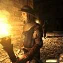
Based on Rebb's work to make the Ambient light run it's own light interaction rather than piggy-back on the main light interaction, I have made a patch that allows you to add the "cubicLight" token to light material defs and switch lighting from the standard shaders to a new cubic_light.vfp shader that uses a cubemap as the projection texture and falloff is done spherically. This "new" shader (2011) was designed by Sikkpin before doom3world.org met it's demise. It also has HL2 ambient style cubemap shading which takes an input cubemap and gives the environment a sort of radiosity approximation based on the values in the input. The main goals of this beta are: 1) Evaluate the functionality (look for bugs) 2) Evaluate the usefulness of each feature 3) Determine whether the current shader is sufficient or if it needs to be modified 4) Create new Light materials and textures to prepare for this feature The shader doesn't have the same features that TDM's main interaction includes (Rim lighting, Fresnel, etc) and instead appears to have been tailored to make the light look as much light HL2 as possible. This means if you use this light type exclusively, your mission wont look like a normal TDM mission. Over the course of the beta, I intend to attempt to fix that but I'm no ARB shader expert so no promises. (If Rebb, SteveL, Revelator, Obsttorte, or JC Denton... etc wish to chime-in I will gladly accept any assistance). In the absence of any help on the shader front, I still believe that this shader could prove useful paired with our normal lighting as it would add more realistic light projections from Desk Lamps or could be used as an alternate outdoor ambient. Here is the download package: https://dl.dropboxusercontent.com/u/17706561/cubicLightPatch.zip Overwrite your TheDarkMod.exe and gamex86.dll in your darkmod install folder. Place the glprogs folder in your darkmod install folder. Place the zzz_ambientcube.pk4 in your darkmod install folder. (This includes materials and cubemap images) Place the maps folder in your darkmod install directory. (This includes a converted version of Sikkpin's demo map without Doom 3 AI) Open the console and invoke: map ambientcube.map You will see the initial area, illuminated by cubemap projected lights. There is some sort of artifact there. I think it might be z-fighting or brush corruption but I couldn't fix it by snapping to grid so this is one of the first things to examine. If you noclip straight up into the sky above this area, you will see the other demo areas with HL2 style lighting. I have found that spawning AI on the platform in these areas produces strange shadowing. I suspect that the geometry of these zones is messing with the shadow calculation so I would like to hear whether the same problem manifests in a map built for TDM. Good luck! (Spooks this is it! )
-
I'm having lighting issues specifically on this mission. This is with soft shadows off, but I have similar problems with them turned on. Upon restart it seems to come up with different lighting issues each time. My settings. https://i.imgur.com/Z4AZLZ6.jpg https://i.imgur.com/wyjwrku.jpg Edit: It would appear my lighting, in general, is broken. I just started "Cleaning Up the Neighbourhood" and it also is broken. Will be posting this in a separate thread appropriately. Edit edit: Just happened in William Steele. My version of TDM seems broken. The lighting was perfectly functional yesterday but I just downloaded some new missions off the list. Is there any way that would have broken things?
-
I hope this isn't a useless thread, just thought it would be constructive to let everyone know about it. I was looking up some TDM related concerns, and accidentally stumbled across another fork of the idTech4 engine. It's called fhDOOM, and it seems to have a lot of neat graphical improvements over the stock engine. eXistence/fhDOOM There are definitely things in there that TDM could consider grabbing! Some important ones highlighted on their front page: Modern renderer based on OpenGL 3.3 core profile. Any up-to-date engine should have this as a norm.Parallax mapping. Not sure if we have this already... I only know the original engine had simple bump mapping.Soft shadows. A heavily desired and long awaited feature.Alpha textures affecting shadows. This allows light to shine through textured grates, which is a very beautiful improvement.Soft particles. This one we already have now however.An example of the old lighting system (ours) versus lighting with shadow mapping (fhDOOM): As the obstacle to new features is almost always finding someone willing to code them, discovering those improvements for our engine is a goldmine... since unless they conflict with any of our changes, I assume they should be easy to just plug into the code. Can any of this good stuff please be considered for inclusion in TDM's version of the engine?
-
I recently saw a post about the functionality of the idTech 6 engine, which brought this suggestion to my attention. It's actually a simple and trivial improvement, although I can imagine people missing it and not thinking about its absence. Also keep in mind I don't know the lighting code of TDM, and everything I say is purely out of observation. Like most engines that use dynamic lighting, TDM tends to have considerable performance issues when a lot of lights are rendered at once. This is often because of shadows and possibly other calculations. A common way to prevent extra computation in the renderer is caching all lights, and only updating each one when necessary. Meaning either the light itself has moved, or something is moving in front of the light. If both the light and the geometry it affects are static, there is nothing to recalculate, which offers a significant performance boost. TDM has a serious problem here: Even if the engine already knows how to cache lights, every torch has a moving light source! If you look closely at a torch, you'll notice its shadows constantly bob around. While this makes sense aesthetically, it also means that light will be recalculated each frame... even if the torch is mounted on a wall and no physical object or NPC is currently moving within its radius. Since most maps use torches and have areas where characters don't walk in front of them, I see a notable performance improvement being lost here. My personal suggestion: First of all, does idTech 4 support light caching for static lights + geometry to begin with? If somehow the original engine didn't have that, I definitely think it should be patched in! Once that's solved, I believe moving light sources for flame based lights should be controlled by a cvar; If people are okay with the performance loss, they can enable that to get bobbing shadows... if not, disable to allow torch lights to be cached and improve overall FPS. An idea to compensate for the visual loss: Can't we use an animated light texture to simulate moving flames altogether, as well as pulsating brightness? The light bobbing looks pretty extreme anyway: In real life, candles have a smooth flame that casts a neat shadow, and shadows don't always move that chaotically even when it's a noisier flame like a campfire.
-
I searched the forum, but couldn't find a good example explaining that blend lights are for and how does it look like compare to normal lights. DarkMod wiki doesn't have info either, D3W is dead, Doom 3 has no blend lights. I noticed RAGE used quite a few of those. So my questions are: 1. What do blend lights look like compare to normal ? (please post an image) 2. What are the common uses for blend lights ? (please post an image) 3. Are there any specifics about preparing assets for blend lights (besides having blendLight key in the material) ? Thanks a bunch!
-
I was looking at some images we have posted after taking some time away from computers entirely for quite an extended period of time and there's one thing I noticed. When we have specific brick or cobblestone textures they look fairly flat and bland. Maybe we should revisit the idea of parallax mapping, it would really improve these textures and actually increase performance because mappers wont need to use polygons to make convincingly 3d cobblestone and brickwork. We don't need parallax for all textures, this is one of the things TDS did right. Some textures had parallax some didn't, why don't we do the same, is this a good or bad idea?