Leaderboard

Popular Content
Showing content with the highest reputation on 01/02/25 in all areas
-
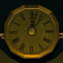
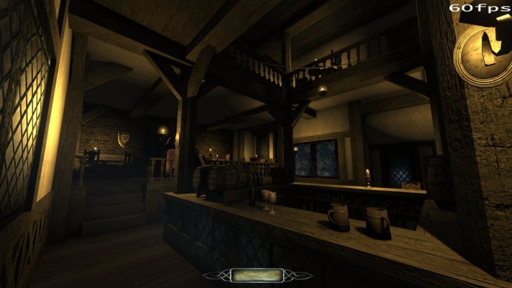
anyone fancy a drink?
(2205.89-1594.95-435.75).thumb.jpg.ac86b077d9a178b2420c5310b9f674d5.jpg) 7 points
7 points -
Changelog of 2.13 development: beta213-05 (rev 17312-10946) * Removed back menuLastGameFrame feature because of random texture popup (post). * Console font minor tweak to avoid artifact under P. * Minor fix for Catalan language. beta213-04 (rev 17306-10940) * Fixed bug with compass + X-ray glasses combination. * Fixed two buttons displayed in menu objectives during game (post). * Added new smoking animation. * Added menuLastGameFrame image to show game footage in in-game main menu (6608). * Changed install/uninstall mission to select/deselect in main menu. * Fixed editor images for HD carpets (6607). * More fixes for Catalan language. beta213-03 (rev 17294-10935) * Fixed crash in WS3 due to script name collision in invisibility potion. * Added praying animation. * Fixed heat-haze shaders with nontrivial Render Scale. * Restored back tonemapping in the menus. * Allow settings hotkeys for gasmine, slowfall, invisibility, made strings translatable. * Fixed double-cursor in game console on 1920x1080 (post). * Applied noise reduction to new vocals for drunk "jack" AI. * Added support for Catalan language. * Fixed UV maps on stove models (6312). beta213-02 (rev 17281-10932) * Fixed HOM-like artifacts in AT1 Lucy and trash frames on TDM start on Linux (post, post). * Disabled tonemap compression curve and reverted settings to 2.12 defaults (post). * Added menu options to disable volumetric lights and parallax mapping. * Fixed varioius issues with largesquare01 materials (6579). * Fixed several issues in the new parallax materials (6604). * Deleted plain_redgreen_design_HD material which references non-existent textures (6601). * Some main menu buttons during game start replaced with generic "Next" (post). * Climbing sounds now depend on material (4991). * Added shaded_lamp_with_grill model (6589). * New fabric_ornate and fabric_fleur materials. beta213-01 (rev 17262-10927) * Improving the fonts continued (thread). * Fixed unwanted mine deployment when player eats the last bit of food in hands (6598). * Removed old hack to fix for scripted savegame crash (4967). * Added a model ext_timber01_window01_empty.lwo (6600). * Fixed missing skin for atdm:ai_revenant_spirit (6595). dev17251-10920 * Added slowfall potion. * Added invisibility potion. * New tonemap settings are now default (post). * Added Texture Quality settings in the main menu. * Added pipes_industrial_modular models. * Minor adjustments to colored versions of gen3 environment maps. * Default value of inv_count is back at 1 to fix issues with inventory counts. * Fixed rare crash on loading collision models (post). * Refactored heatHaze shaders. dev17234-10914 * Added many new high-res materials, half of them with parallax mapping. * Implemented optional HDR compression in tonemapping + other improvements (post). * Implemented interactionSeparator syntax in materials (post). * Added new entityDef: atdm:radio. * Added colored versions of gen3 environment cubemaps for metallic materials. * Added new environment cubemaps: sparkles, studio, blurry. * Added coat_commoner_hanging and coat_inventor_hanging models. * Added mantle_clock_ticking sound. * Improved lightgem calculations while leaning (post). * Fixed regression with double-sided materials (5862). * New sorting of inventory grid items (6592). * Reduced font size of mission list, which allows to see more missions and longer names (post). * Added scrollbar to "notes" of a mission in the main menu. * Optimization: don't render interaction groups with black diffuse & specular. * Improved "scepter" material (thread). * Fixed normal map of ornament_relief_mold_eaglelshield (6585). * More tweaks to starry2 materials. * Made material noshadows: moon_full_shaded, shooting_star, moon_glow. * Added "inv_count" "1" spawnarg to atdm:playertool. * Gas mine now costs 125 instead of 75. * Added min/max builtin functions to game scripts. * Added script events about gravity, health, in-air movement. * Added script events setUserBy, setFrobActionScript. dev17171-10894 * Added entityDef archery_target01 with hit detection, it is now used in Training Mission. * Fixed missing steam_pipe02_straight in Training Mission. * Hiding mouse cursor during briefing in official missions (6576). * Cleaned up the code for extracting interaction groups in material. * Parallax mapping: supported "translate", self-shadows are disabled properly (6571). * Fixed meshes generator_big, generator_small, generator2, warehouse_front_doorframe (6581). * Fixed material on model stove_open02 (6580). * Fixed decals on ext_timber01_window01 (5782). * Improved largesquare01 materials with bumpmap and specular (6579). * Added skybox materials clouds3 and clouds_4_small + prefabs. dev17152-10890 * Major update of Training Mission, including vine arrows (4352). * Added TDM version + engine revision in lower-left corner of main menu. * Experimental implementation of parallax mapping (6571). * Fixed frob interaction with candle holder that's initially extinguished (6577). * Better icons for scrollbar thumb in menu, fixed author search (6339 6570 6449). * Fixed hiding mouse cursor during video briefing/debriefing (6576). * Fixed map immobilization not applied if opening map with inv use key. * Forbid adding missions to download when download is in progress (6368). * Skip disabled bump stages in environment mapping (6572). * Disabled texture compression for light images: falloff and IBL cubemaps. * Minor change in shadow map acne / blur radius computation (6571). * Added banner01_edgar and banner01_viktor banners, along with long versions. * Fixed UV map for longbanner_ragged model (6573). * Added missing jack/drunk_idle13.ogg sample (6507). * Fixed handle_curved02_latch prefab, deleted pull_handle (6286). * Replaced normal map of cobblestone_blue_black with high-res version (6574). * More detailed editor images of some materials (6575). * Added small_dresser_openable prefab. * Added banner_sword + tdm_bannerlong_sword materials. * Increased size of secret message overlay GUI. dev17121-10869 * Massive improvements in mission select & download menus, added search (6339 6570 6449). * Improvements and fixes for "builder priest" animated mesh. * Improvements of idle01 animation. * Improved newspaper01 model (6568). * Added gas mine to "map start pack" prefabs (6559). * Fixed text alignment in save/load menus. * Minor CI/build fixes. dev17104-10844 * Enabled the new system for tracking light value by default (6546). * New light value tracking integration covers ropes and doors + optimized shadow rays (6546). * Added atdm:playertools_gasmine (6559). * Workaround for compiler bug which broke particle collisions with texture layout (post). * Fixed r_showTris: color, values 2 and 3 (6560). * Minor improvements to drunk vocals (6507). * More tweaks to sculpted/girard_relief_pho. dev17095-10833 * Major improvements in drunk AIs: setting "drunk" spawnarg is enough now; new sounds, animation improvements, greetings, etc. (6507). Fixed drunk women AI (5047). * Incorporated stone font updates by Geep (thread). * New footstep sounds for ice and broken glass (6551). * Fixed light culling bug on elongated models with non-identity rotation (6557). * Added new system for tracking light value of entities (6546). It is disabled yet. * Technical change in loading of particle collisions (6546). * Now AI follower settings can be set as spawnargs, added prefab (6552). * Added proper dmap error message if map file contains an entity before worldspawn. * Fixed water_medium_running sound (5384). * Fixed window/metal_irregularpanes_moonlit material. * Fixed wood/boards/rough_boards_scratched (4157). * Fixed wall/ship_wheel model (6549). * Fixed gaps in awning_cloth_01_large model (6550). * Added weather particles with static collisions enabled (6545). * Added a pack of new factory_machines models (6537). * Added fabric/cloth_baize materials (red and purple). * Added window/diamond_pattern01_moonlit_bright material (6133). * Added AO and specular maps to sculpted/girard_relief material. * Added musicbox sound, added prefabs for it and for victrola. * Added wood/panels/mary_panel model. * DarkRadiant now knows about parallelSky param (6496). dev17056-10800 * Supported "efx_preset" spawnarg on location entities (6273, thread). * Fixed rendering of volumetric light and particles in X-ray views (6538). * Fixed rendering of particles in mirrors (6538). * Improved volume estimation for subtitles, very quiet subtitles are hidden (6491). * Fixed bug in idClip::Translation of non-centered models. * Third-party integration greatly reworked for better integration with conan (6253). * Stone/subtitle font improvements by Geep. * Fixed sleeping sounds for drunk AIs (6539), and other sounds for them too (6507). * Fixed missing shadow on endtable_001 model (6288). * Added girard_relief material. Known issues: * Shadows of Northdale Act 1 does not start (6509). (mission has been updated) dev17044-10746 * Supported mission overrides for cvars which are tied to gameplay state (5453). * Fixed crash on start with 32-bit Windows build. * Rebuilt all third-party libraries with conan 2 system (6253). * Reverted improvements of capped FPS to fix video/audio desync (5575). dev17042-10732 * Restored ability to create cvars dynamically, fixing bow in missions (5600). * Fixed issue where .cfg files were saved every frame (5600). * Added sys.getcvarf script event for getting float value of cvar (6530). * Extracted most of constants from weapon scripts into cvars (6530). dev17035-10724 * Support passing information between game and briefing/debriefing GUI via persistent info. Also changed start map & location selection, added on_mission_complete script callback (6509 thread). * New bumpmapped environment mapping is now default (6354). * New behavior of zero sound spawnarg is now default (6346). * Added sound for "charge post" model (6527). * Major refactoring of cvars system to simplify future changes (5600). Known issues: * Bow does not shoot in some missions: thread (only in this dev build) dev17026-10712 * Nested subviews (mirrors, remotes, sky, etc.) now work properly (6434). * Added GUI debriefing state on mission success (6509 thread). * Sound argument override with zero now works properly under cvar (6346 thread). * Environment mapping is same on bumpy and non-bumpy surfaces under cvar (6354 thread). * Default console font size reduced to 5, added lower bound depending on resolution. * Added high-quality versions of panel_carved_rectangles (6515). * Added proper normal map for stainglass_saint_03 (6521). * Fixed DestroyDelay warning when closing objectives. * Fixed the only remaining non-threadsafe cvar (5600). * Minor optimization of depth shader. * Added cm_allocator debug cvar (6505). * Fixed r_lockView when compass is enabled. dev17008-10685 * Enabled shadow features specific to maps implementation (poll). * Auto-detect number of parallel threads to use in jobs system (6503). * Improved parallel images loading, parallelized sounds loading, optimized EAS (6503). * Major improvements in mission loading progress bar (6503). * Core missions are now stored uncompressed in assets SVN (6498). * Deleted a lot of old rendering code under useNewRenderPasses + some cleanup (6271). dev16996-10665 * Environment mapping supports texcoord transforms on bumpmap (6500). * Fully disabled shadows on translucent objects (6490). * Fixed dmap making almost axis-aligned visportals buggy (6480). * com_maxFps no longer quantizes by milliseconds on Windows 8+. * Now Uncapped FPS and Vsync are ON by default. * Supported Vsync control on Linux. * Added set of prototype materials (thread). * Fixes to Stone font to remove stray pixels (post). * Loot candlestick no longer toggle the candle when taken. * Optimized volumetric lights and shadows in the new Training Mission (4352). * Fixed frob_light_holder_toggle_light on entities with both skin_lit and skin_unlit. * Now combination lock supports non-door entities by activating them. * Added low-poly version of hedge model (6481). * Added tiling version of distant_cityscape_01 texture (6487). * Added missing editor image for geometric02_red_end_HD (6492). * Added building_facades/city_district decal material. * Fixed rendering with "r_useScissor 0" (6349). * Added r_lockView debug rendering cvar (thread). * Fixed regression in polygon trace model (5887). * Added a set of lampion light entityDefs.1 point
-
My rig: Nintendo Switch OLED running Linux. This is Linux 64 bit version with box64. Game is hovering around 30fps with mix of low and medium settings. I am almost certain we can run this even more natively and with better results but its great already. Next stop is Android port of idTech4. I would post pictures but they are too big. Come to discord to see them if you really want lol.1 point
-
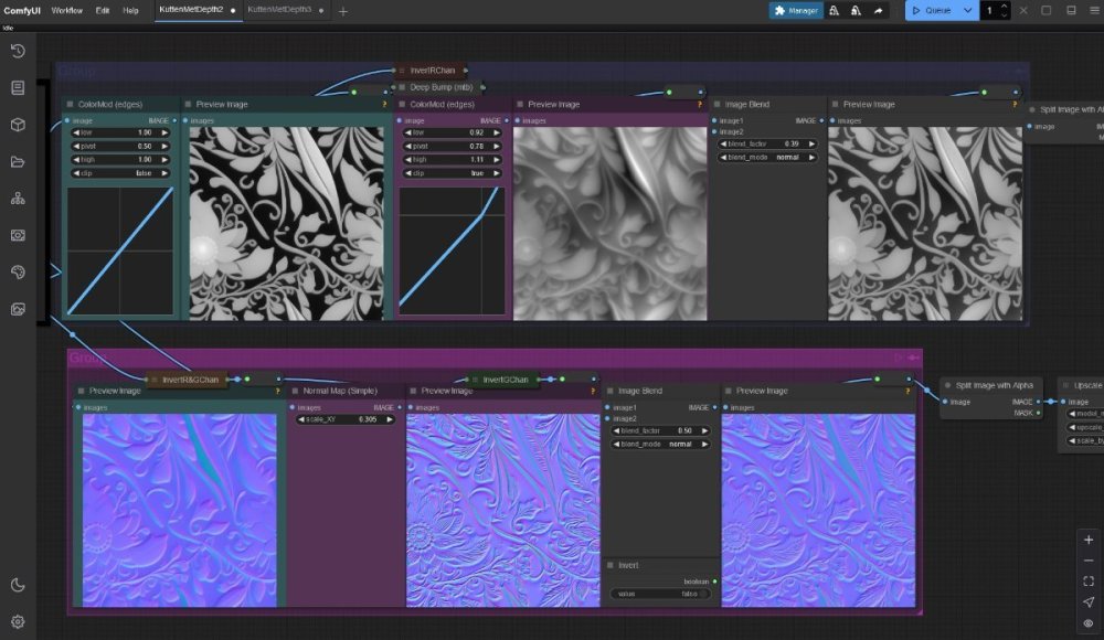
Still working on the comfyUI "workflow". As all was looking very good at first glance, there were some things that didn't work as they should; mainly producing decent seamless tiling height (depth) maps. But I got that figuered out with a trick: Make a 3x3 grid with the diffuse (color) map (scaled to 512 so the combined image is 1536) > make a heightmap of that and crop to the center, so the output is 512 again. And it works (using geowizard nodes that produce a height and normalmap). Added bonus: The seamless tiling normalmap from geowizerd can be converted to a height map with deepbump, that produces seamless heightmaps also, but in a very different way: they can be blended together to get a very decent result. Added bonus 2: The normal map created from the diffuse map with deepbump was already quite good, but now there is the normalmap created by geowizard also, both tiling seamless: They can be blended together (to have more or less detail). Also I added a way to reduce the highlights and shadows from generated images a bit; that is still a problem with generating textures with AI. Prompting: "A floor that looks like a stone wall" works a bit but doesn't work with a door somehow. AI models are trained on images with light coming from above. Althought there are (re)lighting options, they are trained on humans and objects, not on walls and doors and stuff ... so that is still a limitation. Maybe I should train a lora on perpendicular lighted vs top lighted surfaces ... : )
 1 point
 -
Volumetric lights work either with shadow maps or without any shadows at all. I guess without shadows they are pretty pointless for sunlight, so shadows is a must. However, our shadow maps still don't support large lights (which includes parallel), so all of this is rendered with stencil shadows. Moreover, I think the game uses precomputed shadow volumes for you, i.e. computed during dmap. I'm sure there is no hard problem with moving the sun smoothly, but you will lose all the precomputed shadows after the first move. And this can decrease performance even further. And you won't get good result indoors anyway because we don't have global illumination, so you have to fake it manually with local lights. Yes, performance is not good. I can probably take a loot at some mission, maybe there is something to improve, but not too much. And given that I see shadow popping/glitching all over the modern games, I suspect LODing and hacking is somewhat common approach...1 point
-
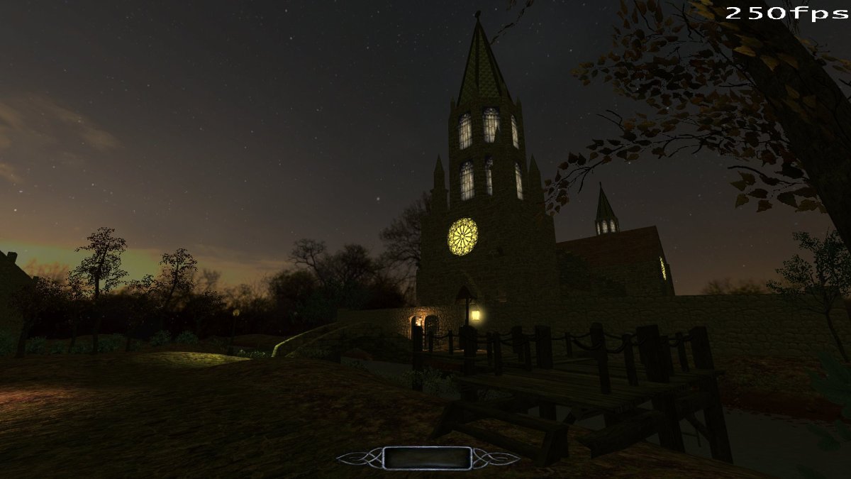
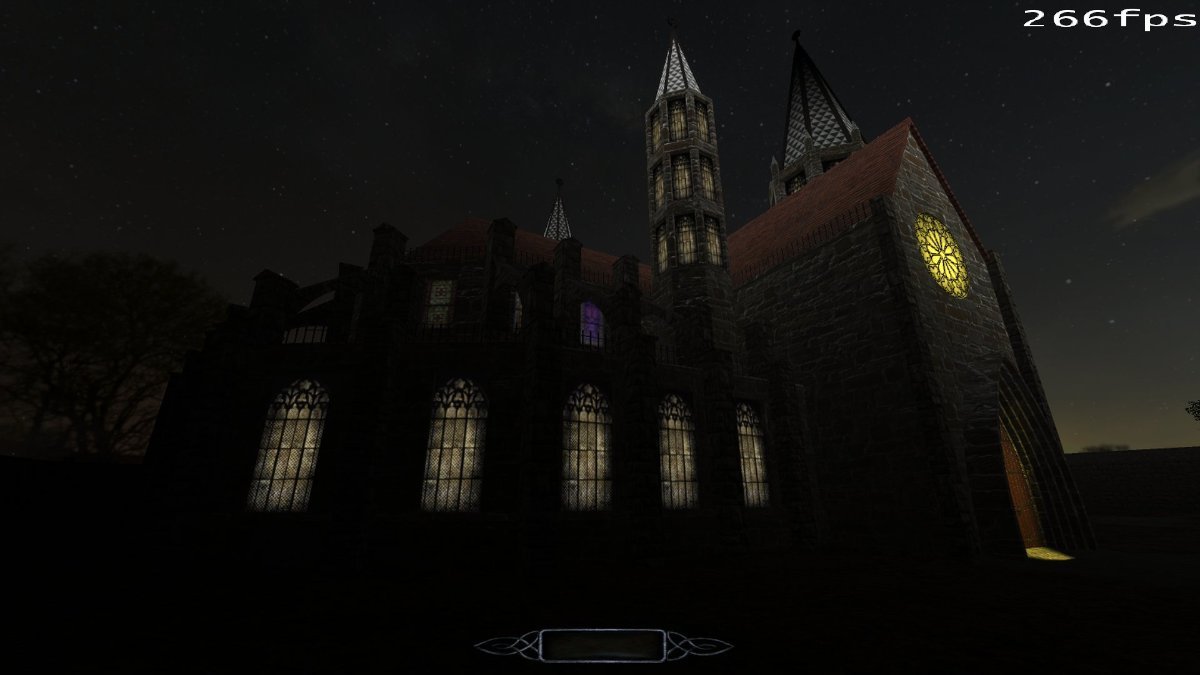
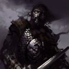
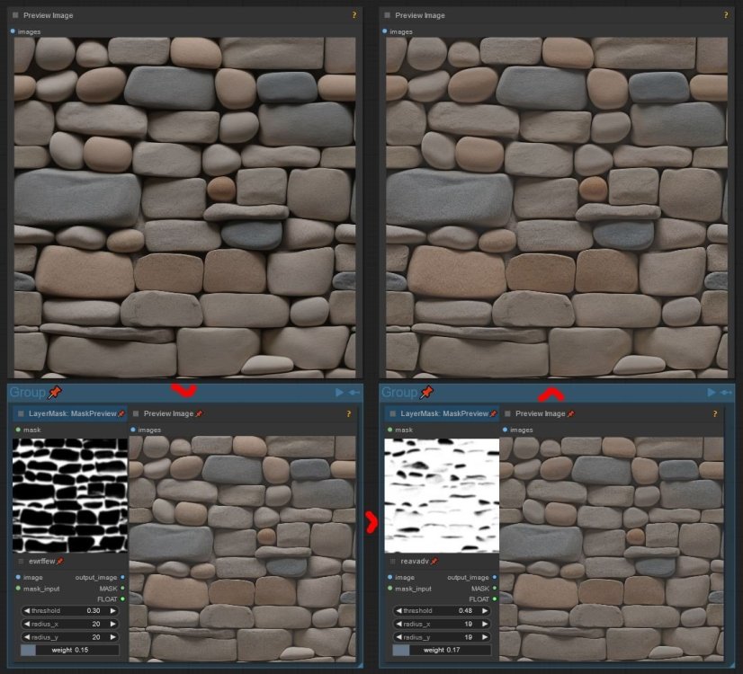
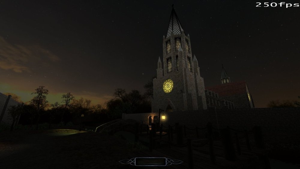
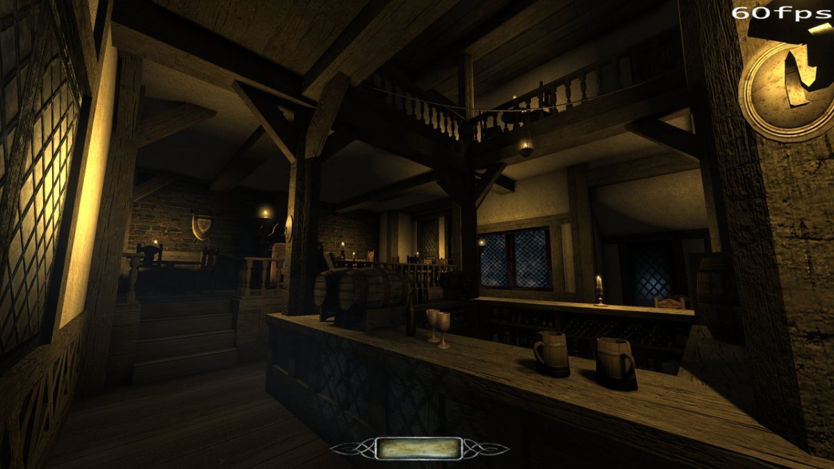
well that was a huge PITA, but it seemed to work. Here's the before and after with the custom ambient cubemap in the second pic instead of ambient_world. The church is a bit too bright, so I'll need to play with it, but at least now the shading isn't so flat. (edit) note that ambientCube will also appear on the interiors. Here's another angle. Now the bumpmap is actually bumpy!
 1 point
 -
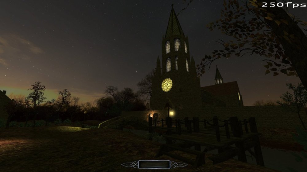
I found myself making what will likely be the first FM to feature a daytime cycle. Not a smooth one where you see the sun go down, that might be doable with a rotating parallel light but difficult and costly on performance: Just objectives toggling the skybox together with the light cubemaps and sun lights. Won't spam too many screenshots here beyond the technical data I'm bumping this for, if anyone wants to see the rest check out this post: What I've observed: First of all parallel lights are very performance intensive even when using parallelsky. Between one sunlight covering the whole map versus some 10 lamps and torches visible at a time, the later is more than 30 FPS faster! I got a lot of FPS back by using the LOD models for building modules as well as noshadows on every module from a low distance, you do see shadows snapping a lot when you navigate but it's gotten close to +90 FPS everywhere so I'll take it. None the less if their performance can be further improved I'd gladly take it! The only real limitation is parallel lights don't seem to support the new volumetric lighting for god rays, which I was hoping to use were it an option. I tried but volumetric_light and volumetric_dust don't seem to mix with parallel and parallelsky and there's no volume. At the most this should be documented on the wiki page so everyone knows they don't work together yet, but is that possible to fix at some point? Beyond that sky lights seem to be working as intended: You must remember to give them the texture lights/tdmnofalloff else the sun dims close to the map edges which I think is intended behavior. I do wonder if scripts have access to the origin vertice of lights and can modify the center, just in case I'm ever crazy enough to attempt a smooth daytime cycle with a rotating sun.1 point
-
This is what I personally know about it: No diffuse means "skip the diffuse path code for this light" essentially means don't add/mix this light color/texture color info unto the surface, only use it as a simple b&w light. No specular is essentially the same but for specular textures, it skips the specular component/code/calculation and makes the light less heavy by removing the specular effect. About performance impact, for today GPU's, I don't think is as important as it was in 2004, but still, I'm sure it does have a small impact on performance, for the better of course, specially if done for many lights, but will also make them way more unrealistic. Btw lights with both no diffuse and nospecular, were used for the "projected shadows" or lights used to project fake "shadows" unto surfaces, this was used in Doom 3 to simulate basic, shadow mapping, for rotating fans and grid materials that use alpha textures, all because stencil shadows ignore those. Now that TDM has real shadow mapping, IMO such lights are less necessary and I wouldn't recommend their use for such effect. Thou lights with no specular and no normal mapping, are still useful for some effects, like simulating casting colored light from painted glass, like something bellow, and they are faster then normal lights:1 point
-
Part 4 Let’s go back to what was said at the beginning of part 3. A workflow with cmftStudio only requires you to stitch a cube cross, a workflow with Lys also requires you to unstitch it. Both of those actions are to be performed in Photoshop. Therefore, I will structure this part thusly: First, I’ll describe how to stitch the cubemap in PS. This is required for both Lys and cmftStudio. Second, I’ll run through the cmftStudio process. At the end of it, you’ll have a game-ready IEM. Third, I will consider Lys and its cube cross export. Fourth, I’ll describe how to unstitch said cross in PS. At the end of this process, rather than the Lys export one, you’ll have a game-ready IEM. Fifth, I will introduce a method to automate renaming the output faces, something you have to do for all three workflows, including the Cubemapgen one explained above. Stitching the Cube Cross in Photoshop Refer back to Fig. 13 at the beginning of the previous part. The cross that Lys accepts is in this format, a horizontal cross unwrapped to the left. Happily, that is also the format cmftStudio takes, so we don’t need to worry about orienting our cross differently. For Cubemapgen, the cross needs to be vertical, unwrapped at top. These steps will yield the first orientation. Step 1: Load the cubemap faces into Photoshop. Refer to [Fig. 6]. These are the input images, and they are ordered in alphabetical order. Alphabetical order is very important for the automated script to work. Select all six files, then drag and drop them into Photoshop. You should have six tabs, ordered alphabetically, like this. [Fig. 19] The six cubemap faces are in separate tabs. t_forward.tga is selected. The image is zoomed in only for illustrative purposes. Select the middle file, t_forward. Step 2: Stitching Like I said, you won’t need to do any of the following sub-steps manually. Photoshop has a macro system, a way to record and playback the actions you take in the app. The Action panel is accessed through the Window menu, or by pressing Alt+F9. [Fig. 20] The Action panel. Your list of Actions may or may not be empty, but you definitely won’t have the ones displayed here. At the end of this part, I will give you this “Cubemap Operations” folder in the form of an .atn file. All you need to do is open the file and the Actions I’ve prepared will get loaded in the panel. Supposing, now, that you have these at the ready, simply run the ‘Stitch Cubemap’ Action. Provided that you did Step 1 correctly, your files are ordered alphabetically and you currently have t_forward open, you’ll get a proper cube cross in a few seconds. Be careful not to overwrite the t_forward tga, save this cross under another, descriptive name, again as a .tga. This completes stitching. The following sub-steps will go into more detail of what the ‘Stitch Cubemap’ Action actually does, in order to better understand the workflow. I’ve gone to great lengths to ensure multiple resolution cubemaps can be transformed through this method, form 16^2 to 4096^2 pixels and any power of two in between. The cubemap for this tutorial has 256^2 px faces. Your cubemap cross should not look misshapen by the end of the Action, but if something does look off, peruse these sub-steps and execute them one by one to troubleshoot your problem. If you have no problems, or don’t plan on working with cubemap faces over 256^2 pixels in size (a size which, for irradiance map conversion purposes, I recommend sticking with), feel free to skip these sub-steps. Step 2.1: Loading the images into a single document In the t_forward document, which you should still be in, double-click the Background layer and turn it to Layer 0. Tab over to t_left. Select All, Copy, tab to t_forward, Paste. t_left will now be Layer 1. Repeat the process with t_down, t_left, t_right and t_up, in that order. At the end, t_up should be at Layer 5. You have six layers with all the faces in one document. Step 2.2.: Align inside canvas Ctrl+Alt+A to Select All Layers. With the move tool active, Align Vertical and Horizontal Centers. The layers must all align and be inside the bounds of the canvas. The Action script aligns centers, if this doesn’t work, try aligning to Top and Left Edges. Step 2.3: Resize canvas Ctrl+Alt+C to open the Canvas Size dialog. With ‘Relative’ checked, resize 200 percent Height. Anchor middle (no change from the default). Ctrl+Alt+C. With ‘Relative’ checked, resize 100% Width. Anchor middle right. Ctrl+Alt+C. With ‘Relative’ checked, resize 100% Width. Anchor middle left. This is the safest way to resize the canvas into a 4:3 ratio (which gives us an 1024x768 px image in this case) without using decimal points and worrying about floating point precision. Step 2.4: Distribute Layers into proper positions Remember that Layer 0 is the t_forward image. It does not need to move. Select Layer 1 (back face) from the layer list. With the move tool shift-click and move it to the far right. Make sure snapping is on so it neatly aligns to the right border of the document, it should be moved +50% to the right, relative to its original position. Repeat the process with the other layers. They should all snap around your middle face. Remember the order you imported the layers by looking at the list of open files up top. Next is t_down, Layer 2, it goes 33.3% down, relatively. Layers 3 and 4 are left and right, respectively, the last layer goes up. Step 2.5: Combine and save The layers should be ordered correctly now. From the Layer menu, either Merge Visible (Ctrl+Shift+E) or Flatten Image. The difference is the former will keep the background of the cube cross transparent. It does not particularly matter if you save the .tga with transparency or not as we’ll be splitting it into faces later anyway. Neither program cares much for the alpha, but I recommend you Flatten Image just in case. --- This concludes the sub-steps for manually stitching a cubemap in Photoshop. You may reproduce these steps in, say, GIMP, but I cannot help you automate the process. There are further external programs, like AutoHotkey, that you can use to automate this workflow, but you can automate anything with AHK by that mindset, so I would better stop before the tutorial gets too off the rails. Whether you use the Actions I’ll provide later or do this by hand, the end result should be a cube cross .tga. This is now ready for import in either cmftStudio or Lys. Let’s go over cmftStudio first. The cmftStudio Workflow [Fig. 21] A screenshot of the cmftStudio UI, from the GitHub readme. cmftStudio’s UI is somewhat non-standard, as I said before, but is not unintuitive. Take a minute or two to familiarise yourself, click around and get acquainted. When you feel a bit more comfortable, direct your attention to the right part of the UI. That is where all the cubemap filtering options are, the only thing of interest on the left side is that “Spheres” button at the very top. Make sure it is pressed, the default, single sphere model, will not preview your IEM. Step 1: Load the cube cross into ctmfStudio On the right-hand side, either click the ‘Edit’ button under the ‘Environment’ tab at the very top, or click on the three thumbnail images under the ‘Preview’ heading. This will open the environment sub-tab [Fig. 21], with Skybox, Radiance, and Irradiance options available to you. Under the Skybox heading, click ‘Browse’ and load your cube cross .tga file into the program. If you have saved it in the /env folder with the other cubemap faces, in order to avoid browsing to it every time you want to reach it you may want to just place the cmftStudio.exe in the folder, as the browse path defaults to “Runtime”, where the .exe is. If you’re working inside an FM folder, remember to remove the .exe before your mission releases, lest you end up distributing the software by mistake. Alternatively, just dump all your stuff on your desktop! It’s cool. Step 2: Filter the cube cross to an IEM The skybox will now appear in the background of the preview window, but the spheres will still preview the default cmftStudio materials. Do not attempt to filter the skybox with the Radiance filter. In my experiences, this either crashes the program or my display driver. Under the Irradiance heading, click ‘Filter skybox with cmft’. Note the resize options available to you. The default gamma processing options provide output comparable to Lys’, which means they are a good standard. Don’t touch them unless you know what you’re doing. Click ‘Process’. The filtering shouldn’t take too long. You can disable “IBL Specular” in the right-hand panel and lower the number of preview spheres from the left to see your irradiance map in motion. You can click the ‘Info’ button to magnify the 2D cross texture. Step 3: Exporting the cube faces Under the Irradiance heading, click ‘Save’. Choose a directory and a descriptive name, save as a .tga, make sure the ‘Output type’ is “FaceList” and ensure you’re saving without an alpha channel. Click save. Note that you may also export the irradiance map how you imported it, as a horizontal cross, but we don’t need to do this. [Fig. 22] The exported irradiance faces in the folder. The files once again need to be renamed, the schema is much the same as with Cubemapgen. After rename, your IEM is ready to be used in-game! There is not much to be criticized with this workflow, cmftStudio allows you to save/load “projects” in order to keep your settings and has better, more user-friendly controls for image adjustments. If I had to spitball, I’d say it has less or an equal number of button-presses-per-IEM-made than Cubemapgen, and provides a better result. The Lys Workflow Here’s a big section title for nothing. I will not describe the process of navigating Lys’ UI and exporting an IEM here, for the sake of brevity. I maintain that you ought not buy the product for just one step, so if you are intent on using Lys for this, I suspect you already own it. Therefore, I need not explain an app you are already familiar with. The result of a Lys export is an irradiance map inside a cube cross. In order to split the cross into its constituent parts, we need to go back to Photoshop. Unstitching the Cube Cross in Photoshop Unstitching requires several extra tools in addition to base PS. The first is Nvidia’s Texture Tools for Photoshop, namely the NVIDIA_CubeMapShuffler script. The second is an improved script for Export Layers to Files. This script, by default in older PS versions, has non-optional enumeration suffixes. The improved version removes them and allows for easier final rename. Download and install both of these, per the instructions provided in the links. Load the irradiance cube cross. Make sure you don’t have any other files open. Recall [Fig. 20], the Action panel. Naturally, to unwrap the cube, run the “Unstitch Cubemap” Action. After the action runs its course, you will have a square image with all the cubemap faces in layers, stacked neatly and named properly. [Fig. 23] The Export Layers to Files dialogue. If yours lacks some of these options, you’ve not installed the improved version properly, or have not removed the old version from its folder. In order to output these to separate files, go to File > Scripts > Export Layers to Files... Export with the settings depicted above, replacing “tIEM” with the name of your irradiance map. You know how .tgas in a folder look by now, so I’ll save you the illustrative image. Suffice it to say that the names on these aren’t quite perfect either. No matter what you do, the Export Layers to Files script will place a hyphen between your “File Name Prefix” string and the name of the layer. At the very least, you don’t need to remember z faces or the like, simply replace the hyphen with an underscore and the IEM is game-ready! This is the extent of the Lys workflow, as you can see it is not very complicated, although the unstitching takes an intermediate amount of time due to the Nvidia scripts. Following, I will explain what the “Unstitch Cubemap”Action does for those who want to know, but be aware that I am far more skeptical to its repurposement in another application. The Nvidia Cubemap Shuffler script is what drives the process and that is a Photoshop-specific utility. Step 1: Rotate the cube cross, use the Shuffler twice First, rotate the image 90° counter-clockwise. The Cubemap Shuffler requires that the cross point downwards. From File > Scripts, run “NVIDIA_CubeMapShuffler”. What it will do is create a new document, cut all six cubemap faces and place them in a horizontal strip format and in seperate layers, named X+, Z-, etc. This isn’t particularly useful. Run the Shuffler again. It will create a third document, “InverseT”, that will reverse the process and “stitch” the cubemap faces back into a cross. Notice, however, that each face will be on its own layer. The net effect here, then, is that by running the Shuffler twice, we’ve separated the faces into layers without having to do any manual selection of our own. The new cube cross is still pointing down. Let’s reset it to original position, rotate the image 90° clockwise. You’ll work in the “InveseT” document now, as far as the other two, the horizontal strip and the original cubemap cross, you can close them without saving. Step 2: Rename layers For easier export, the layers may be renamed to their game-compatible suffixes: forward, back, etc. The list from Cubemapgen will come in handy here again, so refer to that. Step 3: Align and trim With the layers renamed, we need a neat way to stack them and delete all the transparent pixels, returning this 4:3 ratio canvas to a 1:1. Ctrl+Alt+A to Select All Layers. With the move tool selected, Align Top and Left Edges. Deselect the layers. From the ‘Image’ menu, select ‘Trim…’. A surefire solution that does not invoke the Canvas Size dialogue, Trim can crop all transparent pixels out of the picture. Since all the layers now overlay each other in the top left corner, Trimming will crop the image down to contain just them, in a square. You may check off the Top and Left checkboxes in the Trim Away section of the dialogue but it ought not be necessary. This encapsulates the “Unstitch Cubemap” Action. Export through the aforementioned layers to files script. Automating Renaming A final bump in the road that you may noticed here is that we have to manually rename all six, output files, no matter the workflow we use. Luckily, there are many batch renaming applications on the internet. Here I’ll review the one I’ve chosen to use. ReNamer http://www.den4b.com/products/renamer Den4b’s ReNamer is a lightweight, but very flexible tool for non-commercial use under the CC BY-NC-ND 3.0 License. I recommend you download the portable version and I shall provide a mirror, redistribution link, in case the website ever goes down. It is so very easy to learn that I will skip relaying you information you can learn in its tutorial .pdf. Instead, I’ll just provide the three different rules for renaming each workflow’s output for your convenience. I will put them in a “Preset” which can be put in the app through the Presets > Import… option. [Fig. 24] ReNamer’s main window. The output from a workflow, cmftStudio in this case, has been drag-and-dropped, to be renamed. The three rules, above, ensure any one of the three workflows described in this tutorial will get converted properly. You may drag more than one cubemap (i.e. more than six images) in at a time and expedite your work further. Important Tools Cubemap Operations.atn IEM Renaming Rules.rnp As promised, here are the coveted automation files you’ll need. With Photoshop open, double-clicking the .ATN file will add a “Cubemap Operations” folder to your list of Actions. Four actions are provided, the useful stitch/unstitch cubemap ones, and the not so useful “Set Up Guides” ones. These automate placements of preparatory Guides that I had to use while figuring out the process of stitching and unstitching, you may however find them interesting to play with. As for the .RNP, that is the ReNamer Preset file. This concludes the main part of this tutorial. Phew! That was a lot of text now, wasn’t it? Come back to Part 5, where I will give a much needed summarization of all the methods previously explained, clear up some ambiguities I had purposefully left out, and provide yet more resources and mirror links. Part 5 A Summary of Available Workflows I understand that, although you’ve read all of the tutorial so far, you may still feel lost in the wealth of information here provided. As previously stated, I wish to engender a spirit of productivity and efficiency, so allow me to tighten up the instructions I have given you and succinctly relay the discrete steps you need to go through in order to use IEMs in the Dark Mod. Step One: Take an envshot in game. With the six resulting .tga files in your <root>/env folder as your input, you Step Two: Use a cubemap filtering program to get an irradiance environment map. You can use three distinct apps. With CubeMapGen, --- load the inputs one by one --- perform the filtering --- export the output into six .tgas --- use ReNamer to get them game-ready. Skip to step three. Working with cmftStudio/Lys involves making a cube cross in PS first. With Photoshop, --- drag and drop the 6 inputs at once. They should be alphabetically ordered and you should tab to the “forward” face. --- run the “Stitch Cubemap” Action --- save the cube cross as a different image than the “front” face With cmftStudio, --- load the cube cross from the right-hand side --- perform the filtering --- export the irradiance output into a face list of six .tgas, analogous to Cubemapgen --- use ReNamer to get them game-ready. Skip to step three. With Lys, drag the cubemap cross in, Ctrl+E to export the irradiance cross out. Then, back in Photoshop, --- load the irradiance cross, make sure you don’t have any other document tabs open --- run the “Unstitch Cubemap” Action --- File > Scripts > Export Layers to File, use .tga --- use ReNamer to get the files game-ready Step Three: Write a light material. In your materials folder, create a new .mtr file. Write a new light material for an ambientCubicLight and supply the “CameraCubemap” keyword with the name of your irradiance map. For reference, you may wish to copy one of the pre-existing materials that TDM already ships with. Step Four: Place the light in DR and test in-game. Give your light the proper texture from the previous step. Place it roughly in the middle of the recipient scene, or near where you took the envshot. Use “reloadDecls” and “reloadImages” in TDM’s console if need be. Presto! Done. You’ve got an irradiance map illuminating your environment. Practical Concerns Following, I will note a few extra facts and good practices you should employ when using IEMs. The cut and dry part of the tutorial is done, so now we can focus a bit more on the peculiar specifics. The Question of Size For the purposes of this tutorial, all cubemaps, imports and exports, have remained the same size — 256 by 256 pixels. Irradiance maps, however, can get away with much lower. IEMs are by and large just color gradations, so lowering their resolution results in minimal quality loss. In my tests I employed a 16x16 pixel IEM with success! I think this may be too much of an overkill though. Generally, I would recommend you export and use 32x32, 64x64, or 128x128 sized IEMs. As far as the initial envshot, I’d advise to keep it at 512^2 tops. During my tests, I tried to take an envshot that was a 1024^2 but the faces came out glitched… whatever you choose, make sure to look over your envshots first for any graphical artifacts. Another point towards smaller IEMs is that, given that we’re still working with .tga files, the file size stacks up fast. I leave it to you to weigh file size against visual fidelity via experimentations. Speaking of .tga though… The Question of Type and Bit Depth TGA files have a “Type” and bit/color depth. Cubemapgen and cmft save Type 2s while Photoshop exports Type 10s and compresses them with PackBits to boot. I profess to not really knowing what difference these types make, but sure enough, they all seem to work just fine so you shouldn’t worry about it too much. Bit depth though… [Fig. 25, 26] I love Web 1.0 colors. A 16 bit vs. a 24 bit irradiance map. Screen brightened for illustrative purposes. Do not use 16 bit depth! I have made it clear that you don’t need alpha channels in these .tgas, but please be aware of the depth you’re saving with, otherwise you will be greeted with this ugly banding effect. The envshots that the game spits out are 24 bits and that’s what I recommend sticking with, a quick glance at the tooltip or the properties of the file will tell you if your images are in the correct depth. Light Considerations I left the problem of “priming the pump” open in the beginning of Part 2. You may frown at the idea of providing extra set-up in order to take good basemaps for irradiance. Thinking through it logically, however, one must admit that for irradiant light to even exist in a scene, radiant light must be shining from somewhere. In other words, to say that the surfaces of an environment provide diffuse light is to say that they diffuse the point light incident on them. Point light has to exist first, ambient light follows. Of course, it’s not that cut and dry in game. The IEM is just a color gradation so it doesn’t matter how the environment, captured by the envshot cubemap, is lit, or rather what it’s lit with, as long as the colors and brightness resemble incident point light somewhat. As mentioned, for my example cubemap I just artificially brightened the windows with ambient lights, because windows ought to be “bright” and emit a light stong enough to diffuse onto the opposite wall of the corridor. My point here is that you can use whatever types of lights or props you want to capture an envshot cubemap, so long as the final luminance across the scene varies in the way you think irradiant light should spread across the ambient cubic light’s boundaries. This example scene, too, is a bit of a bottom-to-top scenario, as it’s clearly a work in progress. I actually advise you to do your “irradiance map light pass” after your level’s been already built, with big, principal lights and small details set, with brightly textured props and wallpapers chosen. This way, you’ll be capturing the most accurate and “up to date” version of your environment, hopefully minimizing the need for extra set-up. There is a caveat here, however, that we must not gloss over. Recall the cube map tutorial I linked earlier. While outdated, a very pertinent point is made at the end of it. “You have to take into consideration that in contrast to a true reflection, the cube map texture will not react to changes in the environment. So if you for example put the torch out, it will still be lit in the cube map. So it would be more practical to have non-extinguishable lights and no large moveables near the water.” I mentioned that I intended to replace the orange, placeholder light at the end of the corridor with a light fixture, some sort of electrical lamp perhaps. Here is the problem: is this light going to be extinguishable? If so, the IEM will not magically update to turn its orange color off! You must consider the gameplay of your level first and its appearance only later. Every light in the level that the player can extinguish, from candles, to lanterns to fireplaces, should be off when taking an envshot for an IEM. The IEM represents irradiant light from a static environment, so every dynamic, or moving, element that can somehow change the illumination in a scene drastically should be hidden or turned off. Yes, that means that you should be especially wary of brightly-robed Builder priests, like our friend for this tutorial, getting in the way of your envshot captures. IEM Prep Considerations To cut a long explanation short, I recommend you export your IEMs a bit brighter than what you expect to use in game! Remember that the irradiance map from your files is shone through an ambient cubic light placed in the editor, and that is still very much a light, like any other. By default its color is white, which means it can only go down in brightness. What I’m getting at here is that if you have a bright IEM that’s not to your liking, you can simply lower the brightness of the ambient cubic light in DarkRadiant. If the IEM is too dark, however, there is nothing you can do short of either setting the “rgb” keyword in the material file above 1 (which clashes with the “colored” keyword and disables the light from being toggled on and off in-game) or just exporting the irradiance map again (which can get fiddly). To export a brighter IEM, play a little with the image manipulation sliders in your program of choice. Recall, for instance, the gamma parameter sliders in cmftStudio. This is all more of a personal preference than a rule of thumb, but adjusting the color keyvar in DR not only allows you to dim the brightness but also to tint your IEMs on the fly, in the case that you want to “tone map” your scene more consistently. Gameplay vs Looks It’s not controversial to say that it’s important to see where you’re going in a video game. Light, however, carries a distinct connotation for Dark Mod players. In furnishing your levels with ambient cubic lights, you may make it appear too bright for a player to consider it “stealthable”. In fact, it may end being un-stealthable in earnest, with the ambient cubic light contributing far too much brightness to the lightgem. The “ai_see” keyvar is an invaluable help in dividing “gameplay” lights and those that are “just for show”. With ai_see set to 0, a light will not contribute to the lightgem level. Setting ambient cubic lights to “invisible” to the light gem should be done on a case-by-case basis, but we can all agree that an IEM that raises the ambiance of the scene to daylight levels should not leave the lightgem pitch black. Certainly, much deliberation on the part of the individual level designer is needed to ensure that the player doesn’t feel at odds with what they are seeing and what their lightgem is telling them. Scalability Concerns This tutorial has dealt with the problem of providing Dark Mod environments with more gradient, realistic looking ambient lighting through a reasonable workflow that can be undertaken by the intermediate mapper. Lighting one corridor for the purposes of show may have been easy, lighting an entire map is a different issue. The question of the scalability of IBL lighting in TDM is one that is currently beyond the scope of this tutorial. Plainly put, nobody’s put it to the test! How could they? I only informed you about the possibility of this approach just now, didn’t I? I invite you to give this approach a try and share your results here. Since I am so obviously invested in this topic, be assured that I will personally investigate how well this method pans out in building the full level that our dear corridor is but a part of. In a future post, I hope to give you a detailed account of any problems I run in when scaling IEMs to a full level and how I troubleshoot them. I’m aware that you may still be unimpressed with the time-vs-value proposition of the screenshots here provided. Maybe an IEM doesn’t look like it’s worth the effort. Be that as it may, it is just another tool in the toolbox of the industrious level builder. I have omitted several other lighting tricks I supplement my scenes with, purely for the sake of clarity. Keep in mind that in no way has this been a “showcase” of how good an IEM lit scene can look. That, too, I hope to provide once this level’s finished. Speaking of, I should probably stop typing and get back to actually making it. All that builder whistling in the background is getting on my nerves… Important Links and Resources Thank you so much for taking the time to read my tutorial. Below, you will find a list of important links, some repeated from above, some new and some mirror links, just in case. The programs involved: Lys, cmftStudio, Cubemapgen, ReNamer. For Photoshop, you need: Cubemap Operations and additionally, if you plan on using Lys, Nvidia Texture Tools and Improved Export Layers to Files Additional links, including mirrors: ModifiedCubeMapGen.exe A mirror of V1.66 from the Google Code Archive. cmftStudio 32bit Windows binary The GitHub page for cmftStudio does not provide x86 binaries. I had a friend compile the source code for me (and you), here it is. Being compiled from the latest code, this version has some differences to the installations offered on the main page. Fullscreen, for instance, works. Radiance map filtering, however, still seems to be broken. You can go in the .conf file with Notepad and adjust the settings in it, such as RAM allocation &c. cmft.exe cmftStudio is the “GUI counterpart for cmft”. This is the command line tool I previously mentioned. Curiously, downloads in the GitHub page for this project are available for both OSX and Linux, but not Windows. I’ve filled this gap; this is the Windows 64bit binary, again compiled by my friend for the sake of convenience. Note, you do not need this file in order to use cmftStudio! ReNamer 6.9 Mirror link. A zip containing a portable version of ReNamer. Note that I have bundled in the Renaming Rules, so this is a two-in-one download. Nvidia Photoshop Plugins, 32bit and 64bit versions. Mirrors of the downloads available on Nvidia’s website. Export Layers to Files.jsx Mirror of the Gist file above. [Fig. 27] May The Builder bless you with slick and efficient work.1 point
(2205.89-1594.95-435.75).jpg.98f4f6c4c4cb2c79e3263ced87c26f02.jpg)