Search the Community
Searched results for '/tags/forums/blender lwo export/' or tags 'forums/blender lwo export/q=/tags/forums/blender lwo export/&'.
-
I'd like to follow up on an earlier post, that keeps with the simple approach of retaining a fixed subtitle fieldwidth. Regarding about how one might test that a subtitle fieldwidth is "just right" for a given subtitle-line character limit (e.g., 42/line), font, and font scale, here's what I would suggest. Using dummy sound files, create a set of about 100 "worst likely case" subtitles that are exactly the length of the character limit. These are directly derived from the corpus of existing "story" and "speech" subtitles. Turn this set into 100 sound shaders for another version of my testSubtitles... program (with the desired fieldwidth, font, and font scale under test), and step through them. What you are looking to achieve is NO auto-wrap from the first to second line. If you get auto-wrap, then adjust the font scale and/or fieldwidth and iterate until good. This gives assurance about "worst likely cases", not "worst possible case", e.g, 42 W's in a row. Details: Suppose you have a function that takes a subtitle string and a font, and returns the "draw length" of that string in internal scale-independent font units, that is, pre-scaling/rendering. It's just a summation of lookups into the appropriate static character-width table (assuming kerning is not an issue). Because we will be using the calculated value just to rank the strings for "worse-ness", the "font unit" is arbitrary. [ @stgatilov, maybe you could provide me with such a function in C++? Then I could do what follows. ] OK, so that is embedded into a program that is turned loose on the existing subtitles, to: look for 2-line subtitles (in inline or srt form) where the lines together exceed the character limit convert those to a single string by replacing the linebreak with a space truncate them to the character limit calculate the "draw length" of each export the strings and their draw lengths into a csv (along with a field indicating the source) Do that for each available subtitle source (FM or stock barks), and import all the .csv files as sets of rows in a spreadsheet. Then sort the rows by draw length and deduplicate (ignoring source). Take the 100 "worst likely case" rows, export them, and turn them (using techniques already developed) into sound shaders for the testSubtitles... program. So, a bit of work, but you get assurance that you've optimized things to minimize future problems.
-
Tutorial: Image-Based Lighting Workflows for TDM
Spooks replied to Spooks's topic in TDM Editors Guild
Part 4 Let’s go back to what was said at the beginning of part 3. A workflow with cmftStudio only requires you to stitch a cube cross, a workflow with Lys also requires you to unstitch it. Both of those actions are to be performed in Photoshop. Therefore, I will structure this part thusly: First, I’ll describe how to stitch the cubemap in PS. This is required for both Lys and cmftStudio. Second, I’ll run through the cmftStudio process. At the end of it, you’ll have a game-ready IEM. Third, I will consider Lys and its cube cross export. Fourth, I’ll describe how to unstitch said cross in PS. At the end of this process, rather than the Lys export one, you’ll have a game-ready IEM. Fifth, I will introduce a method to automate renaming the output faces, something you have to do for all three workflows, including the Cubemapgen one explained above. Stitching the Cube Cross in Photoshop Refer back to Fig. 13 at the beginning of the previous part. The cross that Lys accepts is in this format, a horizontal cross unwrapped to the left. Happily, that is also the format cmftStudio takes, so we don’t need to worry about orienting our cross differently. For Cubemapgen, the cross needs to be vertical, unwrapped at top. These steps will yield the first orientation. Step 1: Load the cubemap faces into Photoshop. Refer to [Fig. 6]. These are the input images, and they are ordered in alphabetical order. Alphabetical order is very important for the automated script to work. Select all six files, then drag and drop them into Photoshop. You should have six tabs, ordered alphabetically, like this. [Fig. 19] The six cubemap faces are in separate tabs. t_forward.tga is selected. The image is zoomed in only for illustrative purposes. Select the middle file, t_forward. Step 2: Stitching Like I said, you won’t need to do any of the following sub-steps manually. Photoshop has a macro system, a way to record and playback the actions you take in the app. The Action panel is accessed through the Window menu, or by pressing Alt+F9. [Fig. 20] The Action panel. Your list of Actions may or may not be empty, but you definitely won’t have the ones displayed here. At the end of this part, I will give you this “Cubemap Operations” folder in the form of an .atn file. All you need to do is open the file and the Actions I’ve prepared will get loaded in the panel. Supposing, now, that you have these at the ready, simply run the ‘Stitch Cubemap’ Action. Provided that you did Step 1 correctly, your files are ordered alphabetically and you currently have t_forward open, you’ll get a proper cube cross in a few seconds. Be careful not to overwrite the t_forward tga, save this cross under another, descriptive name, again as a .tga. This completes stitching. The following sub-steps will go into more detail of what the ‘Stitch Cubemap’ Action actually does, in order to better understand the workflow. I’ve gone to great lengths to ensure multiple resolution cubemaps can be transformed through this method, form 16^2 to 4096^2 pixels and any power of two in between. The cubemap for this tutorial has 256^2 px faces. Your cubemap cross should not look misshapen by the end of the Action, but if something does look off, peruse these sub-steps and execute them one by one to troubleshoot your problem. If you have no problems, or don’t plan on working with cubemap faces over 256^2 pixels in size (a size which, for irradiance map conversion purposes, I recommend sticking with), feel free to skip these sub-steps. Step 2.1: Loading the images into a single document In the t_forward document, which you should still be in, double-click the Background layer and turn it to Layer 0. Tab over to t_left. Select All, Copy, tab to t_forward, Paste. t_left will now be Layer 1. Repeat the process with t_down, t_left, t_right and t_up, in that order. At the end, t_up should be at Layer 5. You have six layers with all the faces in one document. Step 2.2.: Align inside canvas Ctrl+Alt+A to Select All Layers. With the move tool active, Align Vertical and Horizontal Centers. The layers must all align and be inside the bounds of the canvas. The Action script aligns centers, if this doesn’t work, try aligning to Top and Left Edges. Step 2.3: Resize canvas Ctrl+Alt+C to open the Canvas Size dialog. With ‘Relative’ checked, resize 200 percent Height. Anchor middle (no change from the default). Ctrl+Alt+C. With ‘Relative’ checked, resize 100% Width. Anchor middle right. Ctrl+Alt+C. With ‘Relative’ checked, resize 100% Width. Anchor middle left. This is the safest way to resize the canvas into a 4:3 ratio (which gives us an 1024x768 px image in this case) without using decimal points and worrying about floating point precision. Step 2.4: Distribute Layers into proper positions Remember that Layer 0 is the t_forward image. It does not need to move. Select Layer 1 (back face) from the layer list. With the move tool shift-click and move it to the far right. Make sure snapping is on so it neatly aligns to the right border of the document, it should be moved +50% to the right, relative to its original position. Repeat the process with the other layers. They should all snap around your middle face. Remember the order you imported the layers by looking at the list of open files up top. Next is t_down, Layer 2, it goes 33.3% down, relatively. Layers 3 and 4 are left and right, respectively, the last layer goes up. Step 2.5: Combine and save The layers should be ordered correctly now. From the Layer menu, either Merge Visible (Ctrl+Shift+E) or Flatten Image. The difference is the former will keep the background of the cube cross transparent. It does not particularly matter if you save the .tga with transparency or not as we’ll be splitting it into faces later anyway. Neither program cares much for the alpha, but I recommend you Flatten Image just in case. --- This concludes the sub-steps for manually stitching a cubemap in Photoshop. You may reproduce these steps in, say, GIMP, but I cannot help you automate the process. There are further external programs, like AutoHotkey, that you can use to automate this workflow, but you can automate anything with AHK by that mindset, so I would better stop before the tutorial gets too off the rails. Whether you use the Actions I’ll provide later or do this by hand, the end result should be a cube cross .tga. This is now ready for import in either cmftStudio or Lys. Let’s go over cmftStudio first. The cmftStudio Workflow [Fig. 21] A screenshot of the cmftStudio UI, from the GitHub readme. cmftStudio’s UI is somewhat non-standard, as I said before, but is not unintuitive. Take a minute or two to familiarise yourself, click around and get acquainted. When you feel a bit more comfortable, direct your attention to the right part of the UI. That is where all the cubemap filtering options are, the only thing of interest on the left side is that “Spheres” button at the very top. Make sure it is pressed, the default, single sphere model, will not preview your IEM. Step 1: Load the cube cross into ctmfStudio On the right-hand side, either click the ‘Edit’ button under the ‘Environment’ tab at the very top, or click on the three thumbnail images under the ‘Preview’ heading. This will open the environment sub-tab [Fig. 21], with Skybox, Radiance, and Irradiance options available to you. Under the Skybox heading, click ‘Browse’ and load your cube cross .tga file into the program. If you have saved it in the /env folder with the other cubemap faces, in order to avoid browsing to it every time you want to reach it you may want to just place the cmftStudio.exe in the folder, as the browse path defaults to “Runtime”, where the .exe is. If you’re working inside an FM folder, remember to remove the .exe before your mission releases, lest you end up distributing the software by mistake. Alternatively, just dump all your stuff on your desktop! It’s cool. Step 2: Filter the cube cross to an IEM The skybox will now appear in the background of the preview window, but the spheres will still preview the default cmftStudio materials. Do not attempt to filter the skybox with the Radiance filter. In my experiences, this either crashes the program or my display driver. Under the Irradiance heading, click ‘Filter skybox with cmft’. Note the resize options available to you. The default gamma processing options provide output comparable to Lys’, which means they are a good standard. Don’t touch them unless you know what you’re doing. Click ‘Process’. The filtering shouldn’t take too long. You can disable “IBL Specular” in the right-hand panel and lower the number of preview spheres from the left to see your irradiance map in motion. You can click the ‘Info’ button to magnify the 2D cross texture. Step 3: Exporting the cube faces Under the Irradiance heading, click ‘Save’. Choose a directory and a descriptive name, save as a .tga, make sure the ‘Output type’ is “FaceList” and ensure you’re saving without an alpha channel. Click save. Note that you may also export the irradiance map how you imported it, as a horizontal cross, but we don’t need to do this. [Fig. 22] The exported irradiance faces in the folder. The files once again need to be renamed, the schema is much the same as with Cubemapgen. After rename, your IEM is ready to be used in-game! There is not much to be criticized with this workflow, cmftStudio allows you to save/load “projects” in order to keep your settings and has better, more user-friendly controls for image adjustments. If I had to spitball, I’d say it has less or an equal number of button-presses-per-IEM-made than Cubemapgen, and provides a better result. The Lys Workflow Here’s a big section title for nothing. I will not describe the process of navigating Lys’ UI and exporting an IEM here, for the sake of brevity. I maintain that you ought not buy the product for just one step, so if you are intent on using Lys for this, I suspect you already own it. Therefore, I need not explain an app you are already familiar with. The result of a Lys export is an irradiance map inside a cube cross. In order to split the cross into its constituent parts, we need to go back to Photoshop. Unstitching the Cube Cross in Photoshop Unstitching requires several extra tools in addition to base PS. The first is Nvidia’s Texture Tools for Photoshop, namely the NVIDIA_CubeMapShuffler script. The second is an improved script for Export Layers to Files. This script, by default in older PS versions, has non-optional enumeration suffixes. The improved version removes them and allows for easier final rename. Download and install both of these, per the instructions provided in the links. Load the irradiance cube cross. Make sure you don’t have any other files open. Recall [Fig. 20], the Action panel. Naturally, to unwrap the cube, run the “Unstitch Cubemap” Action. After the action runs its course, you will have a square image with all the cubemap faces in layers, stacked neatly and named properly. [Fig. 23] The Export Layers to Files dialogue. If yours lacks some of these options, you’ve not installed the improved version properly, or have not removed the old version from its folder. In order to output these to separate files, go to File > Scripts > Export Layers to Files... Export with the settings depicted above, replacing “tIEM” with the name of your irradiance map. You know how .tgas in a folder look by now, so I’ll save you the illustrative image. Suffice it to say that the names on these aren’t quite perfect either. No matter what you do, the Export Layers to Files script will place a hyphen between your “File Name Prefix” string and the name of the layer. At the very least, you don’t need to remember z faces or the like, simply replace the hyphen with an underscore and the IEM is game-ready! This is the extent of the Lys workflow, as you can see it is not very complicated, although the unstitching takes an intermediate amount of time due to the Nvidia scripts. Following, I will explain what the “Unstitch Cubemap”Action does for those who want to know, but be aware that I am far more skeptical to its repurposement in another application. The Nvidia Cubemap Shuffler script is what drives the process and that is a Photoshop-specific utility. Step 1: Rotate the cube cross, use the Shuffler twice First, rotate the image 90° counter-clockwise. The Cubemap Shuffler requires that the cross point downwards. From File > Scripts, run “NVIDIA_CubeMapShuffler”. What it will do is create a new document, cut all six cubemap faces and place them in a horizontal strip format and in seperate layers, named X+, Z-, etc. This isn’t particularly useful. Run the Shuffler again. It will create a third document, “InverseT”, that will reverse the process and “stitch” the cubemap faces back into a cross. Notice, however, that each face will be on its own layer. The net effect here, then, is that by running the Shuffler twice, we’ve separated the faces into layers without having to do any manual selection of our own. The new cube cross is still pointing down. Let’s reset it to original position, rotate the image 90° clockwise. You’ll work in the “InveseT” document now, as far as the other two, the horizontal strip and the original cubemap cross, you can close them without saving. Step 2: Rename layers For easier export, the layers may be renamed to their game-compatible suffixes: forward, back, etc. The list from Cubemapgen will come in handy here again, so refer to that. Step 3: Align and trim With the layers renamed, we need a neat way to stack them and delete all the transparent pixels, returning this 4:3 ratio canvas to a 1:1. Ctrl+Alt+A to Select All Layers. With the move tool selected, Align Top and Left Edges. Deselect the layers. From the ‘Image’ menu, select ‘Trim…’. A surefire solution that does not invoke the Canvas Size dialogue, Trim can crop all transparent pixels out of the picture. Since all the layers now overlay each other in the top left corner, Trimming will crop the image down to contain just them, in a square. You may check off the Top and Left checkboxes in the Trim Away section of the dialogue but it ought not be necessary. This encapsulates the “Unstitch Cubemap” Action. Export through the aforementioned layers to files script. Automating Renaming A final bump in the road that you may noticed here is that we have to manually rename all six, output files, no matter the workflow we use. Luckily, there are many batch renaming applications on the internet. Here I’ll review the one I’ve chosen to use. ReNamer http://www.den4b.com/products/renamer Den4b’s ReNamer is a lightweight, but very flexible tool for non-commercial use under the CC BY-NC-ND 3.0 License. I recommend you download the portable version and I shall provide a mirror, redistribution link, in case the website ever goes down. It is so very easy to learn that I will skip relaying you information you can learn in its tutorial .pdf. Instead, I’ll just provide the three different rules for renaming each workflow’s output for your convenience. I will put them in a “Preset” which can be put in the app through the Presets > Import… option. [Fig. 24] ReNamer’s main window. The output from a workflow, cmftStudio in this case, has been drag-and-dropped, to be renamed. The three rules, above, ensure any one of the three workflows described in this tutorial will get converted properly. You may drag more than one cubemap (i.e. more than six images) in at a time and expedite your work further. Important Tools Cubemap Operations.atn IEM Renaming Rules.rnp As promised, here are the coveted automation files you’ll need. With Photoshop open, double-clicking the .ATN file will add a “Cubemap Operations” folder to your list of Actions. Four actions are provided, the useful stitch/unstitch cubemap ones, and the not so useful “Set Up Guides” ones. These automate placements of preparatory Guides that I had to use while figuring out the process of stitching and unstitching, you may however find them interesting to play with. As for the .RNP, that is the ReNamer Preset file. This concludes the main part of this tutorial. Phew! That was a lot of text now, wasn’t it? Come back to Part 5, where I will give a much needed summarization of all the methods previously explained, clear up some ambiguities I had purposefully left out, and provide yet more resources and mirror links. Part 5 A Summary of Available Workflows I understand that, although you’ve read all of the tutorial so far, you may still feel lost in the wealth of information here provided. As previously stated, I wish to engender a spirit of productivity and efficiency, so allow me to tighten up the instructions I have given you and succinctly relay the discrete steps you need to go through in order to use IEMs in the Dark Mod. Step One: Take an envshot in game. With the six resulting .tga files in your <root>/env folder as your input, you Step Two: Use a cubemap filtering program to get an irradiance environment map. You can use three distinct apps. With CubeMapGen, --- load the inputs one by one --- perform the filtering --- export the output into six .tgas --- use ReNamer to get them game-ready. Skip to step three. Working with cmftStudio/Lys involves making a cube cross in PS first. With Photoshop, --- drag and drop the 6 inputs at once. They should be alphabetically ordered and you should tab to the “forward” face. --- run the “Stitch Cubemap” Action --- save the cube cross as a different image than the “front” face With cmftStudio, --- load the cube cross from the right-hand side --- perform the filtering --- export the irradiance output into a face list of six .tgas, analogous to Cubemapgen --- use ReNamer to get them game-ready. Skip to step three. With Lys, drag the cubemap cross in, Ctrl+E to export the irradiance cross out. Then, back in Photoshop, --- load the irradiance cross, make sure you don’t have any other document tabs open --- run the “Unstitch Cubemap” Action --- File > Scripts > Export Layers to File, use .tga --- use ReNamer to get the files game-ready Step Three: Write a light material. In your materials folder, create a new .mtr file. Write a new light material for an ambientCubicLight and supply the “CameraCubemap” keyword with the name of your irradiance map. For reference, you may wish to copy one of the pre-existing materials that TDM already ships with. Step Four: Place the light in DR and test in-game. Give your light the proper texture from the previous step. Place it roughly in the middle of the recipient scene, or near where you took the envshot. Use “reloadDecls” and “reloadImages” in TDM’s console if need be. Presto! Done. You’ve got an irradiance map illuminating your environment. Practical Concerns Following, I will note a few extra facts and good practices you should employ when using IEMs. The cut and dry part of the tutorial is done, so now we can focus a bit more on the peculiar specifics. The Question of Size For the purposes of this tutorial, all cubemaps, imports and exports, have remained the same size — 256 by 256 pixels. Irradiance maps, however, can get away with much lower. IEMs are by and large just color gradations, so lowering their resolution results in minimal quality loss. In my tests I employed a 16x16 pixel IEM with success! I think this may be too much of an overkill though. Generally, I would recommend you export and use 32x32, 64x64, or 128x128 sized IEMs. As far as the initial envshot, I’d advise to keep it at 512^2 tops. During my tests, I tried to take an envshot that was a 1024^2 but the faces came out glitched… whatever you choose, make sure to look over your envshots first for any graphical artifacts. Another point towards smaller IEMs is that, given that we’re still working with .tga files, the file size stacks up fast. I leave it to you to weigh file size against visual fidelity via experimentations. Speaking of .tga though… The Question of Type and Bit Depth TGA files have a “Type” and bit/color depth. Cubemapgen and cmft save Type 2s while Photoshop exports Type 10s and compresses them with PackBits to boot. I profess to not really knowing what difference these types make, but sure enough, they all seem to work just fine so you shouldn’t worry about it too much. Bit depth though… [Fig. 25, 26] I love Web 1.0 colors. A 16 bit vs. a 24 bit irradiance map. Screen brightened for illustrative purposes. Do not use 16 bit depth! I have made it clear that you don’t need alpha channels in these .tgas, but please be aware of the depth you’re saving with, otherwise you will be greeted with this ugly banding effect. The envshots that the game spits out are 24 bits and that’s what I recommend sticking with, a quick glance at the tooltip or the properties of the file will tell you if your images are in the correct depth. Light Considerations I left the problem of “priming the pump” open in the beginning of Part 2. You may frown at the idea of providing extra set-up in order to take good basemaps for irradiance. Thinking through it logically, however, one must admit that for irradiant light to even exist in a scene, radiant light must be shining from somewhere. In other words, to say that the surfaces of an environment provide diffuse light is to say that they diffuse the point light incident on them. Point light has to exist first, ambient light follows. Of course, it’s not that cut and dry in game. The IEM is just a color gradation so it doesn’t matter how the environment, captured by the envshot cubemap, is lit, or rather what it’s lit with, as long as the colors and brightness resemble incident point light somewhat. As mentioned, for my example cubemap I just artificially brightened the windows with ambient lights, because windows ought to be “bright” and emit a light stong enough to diffuse onto the opposite wall of the corridor. My point here is that you can use whatever types of lights or props you want to capture an envshot cubemap, so long as the final luminance across the scene varies in the way you think irradiant light should spread across the ambient cubic light’s boundaries. This example scene, too, is a bit of a bottom-to-top scenario, as it’s clearly a work in progress. I actually advise you to do your “irradiance map light pass” after your level’s been already built, with big, principal lights and small details set, with brightly textured props and wallpapers chosen. This way, you’ll be capturing the most accurate and “up to date” version of your environment, hopefully minimizing the need for extra set-up. There is a caveat here, however, that we must not gloss over. Recall the cube map tutorial I linked earlier. While outdated, a very pertinent point is made at the end of it. “You have to take into consideration that in contrast to a true reflection, the cube map texture will not react to changes in the environment. So if you for example put the torch out, it will still be lit in the cube map. So it would be more practical to have non-extinguishable lights and no large moveables near the water.” I mentioned that I intended to replace the orange, placeholder light at the end of the corridor with a light fixture, some sort of electrical lamp perhaps. Here is the problem: is this light going to be extinguishable? If so, the IEM will not magically update to turn its orange color off! You must consider the gameplay of your level first and its appearance only later. Every light in the level that the player can extinguish, from candles, to lanterns to fireplaces, should be off when taking an envshot for an IEM. The IEM represents irradiant light from a static environment, so every dynamic, or moving, element that can somehow change the illumination in a scene drastically should be hidden or turned off. Yes, that means that you should be especially wary of brightly-robed Builder priests, like our friend for this tutorial, getting in the way of your envshot captures. IEM Prep Considerations To cut a long explanation short, I recommend you export your IEMs a bit brighter than what you expect to use in game! Remember that the irradiance map from your files is shone through an ambient cubic light placed in the editor, and that is still very much a light, like any other. By default its color is white, which means it can only go down in brightness. What I’m getting at here is that if you have a bright IEM that’s not to your liking, you can simply lower the brightness of the ambient cubic light in DarkRadiant. If the IEM is too dark, however, there is nothing you can do short of either setting the “rgb” keyword in the material file above 1 (which clashes with the “colored” keyword and disables the light from being toggled on and off in-game) or just exporting the irradiance map again (which can get fiddly). To export a brighter IEM, play a little with the image manipulation sliders in your program of choice. Recall, for instance, the gamma parameter sliders in cmftStudio. This is all more of a personal preference than a rule of thumb, but adjusting the color keyvar in DR not only allows you to dim the brightness but also to tint your IEMs on the fly, in the case that you want to “tone map” your scene more consistently. Gameplay vs Looks It’s not controversial to say that it’s important to see where you’re going in a video game. Light, however, carries a distinct connotation for Dark Mod players. In furnishing your levels with ambient cubic lights, you may make it appear too bright for a player to consider it “stealthable”. In fact, it may end being un-stealthable in earnest, with the ambient cubic light contributing far too much brightness to the lightgem. The “ai_see” keyvar is an invaluable help in dividing “gameplay” lights and those that are “just for show”. With ai_see set to 0, a light will not contribute to the lightgem level. Setting ambient cubic lights to “invisible” to the light gem should be done on a case-by-case basis, but we can all agree that an IEM that raises the ambiance of the scene to daylight levels should not leave the lightgem pitch black. Certainly, much deliberation on the part of the individual level designer is needed to ensure that the player doesn’t feel at odds with what they are seeing and what their lightgem is telling them. Scalability Concerns This tutorial has dealt with the problem of providing Dark Mod environments with more gradient, realistic looking ambient lighting through a reasonable workflow that can be undertaken by the intermediate mapper. Lighting one corridor for the purposes of show may have been easy, lighting an entire map is a different issue. The question of the scalability of IBL lighting in TDM is one that is currently beyond the scope of this tutorial. Plainly put, nobody’s put it to the test! How could they? I only informed you about the possibility of this approach just now, didn’t I? I invite you to give this approach a try and share your results here. Since I am so obviously invested in this topic, be assured that I will personally investigate how well this method pans out in building the full level that our dear corridor is but a part of. In a future post, I hope to give you a detailed account of any problems I run in when scaling IEMs to a full level and how I troubleshoot them. I’m aware that you may still be unimpressed with the time-vs-value proposition of the screenshots here provided. Maybe an IEM doesn’t look like it’s worth the effort. Be that as it may, it is just another tool in the toolbox of the industrious level builder. I have omitted several other lighting tricks I supplement my scenes with, purely for the sake of clarity. Keep in mind that in no way has this been a “showcase” of how good an IEM lit scene can look. That, too, I hope to provide once this level’s finished. Speaking of, I should probably stop typing and get back to actually making it. All that builder whistling in the background is getting on my nerves… Important Links and Resources Thank you so much for taking the time to read my tutorial. Below, you will find a list of important links, some repeated from above, some new and some mirror links, just in case. The programs involved: Lys, cmftStudio, Cubemapgen, ReNamer. For Photoshop, you need: Cubemap Operations and additionally, if you plan on using Lys, Nvidia Texture Tools and Improved Export Layers to Files Additional links, including mirrors: ModifiedCubeMapGen.exe A mirror of V1.66 from the Google Code Archive. cmftStudio 32bit Windows binary The GitHub page for cmftStudio does not provide x86 binaries. I had a friend compile the source code for me (and you), here it is. Being compiled from the latest code, this version has some differences to the installations offered on the main page. Fullscreen, for instance, works. Radiance map filtering, however, still seems to be broken. You can go in the .conf file with Notepad and adjust the settings in it, such as RAM allocation &c. cmft.exe cmftStudio is the “GUI counterpart for cmft”. This is the command line tool I previously mentioned. Curiously, downloads in the GitHub page for this project are available for both OSX and Linux, but not Windows. I’ve filled this gap; this is the Windows 64bit binary, again compiled by my friend for the sake of convenience. Note, you do not need this file in order to use cmftStudio! ReNamer 6.9 Mirror link. A zip containing a portable version of ReNamer. Note that I have bundled in the Renaming Rules, so this is a two-in-one download. Nvidia Photoshop Plugins, 32bit and 64bit versions. Mirrors of the downloads available on Nvidia’s website. Export Layers to Files.jsx Mirror of the Gist file above. [Fig. 27] May The Builder bless you with slick and efficient work. -
Afaik Doom 3 does support smoothing in lwo but is based in material angle smoothing like in Lightwave and MODO not 3DMax based smoothing groups. Personally I don't see what more you can use lwo for in TDM, does it support vertex animation? I'm asking because for bones you have MD5 and for vertex animation you have MD3 but is a very old format with very few tool support. I don't know how generic you can make lwo, so other tools can use its full power, IMO is really useful for those using Modo and old lightwave but for any others I cannot say how good is the format supported, in the case of MODO is the second best supported format after the main .lxo format, in the case of Maya/3DMax and Blender afaik have no support at all for it, unless you use a plugging or addon. IMO lwo support in idtech 4, as a static format, was really for MODO, why, because Seneca one of the main idSoftware 3D artists, is a Modo fan/aficionado and I bet he pushed for the inclusion of the format in the engine. But today I would recommend .fbx instead more universal support. Tools that I personally know support Lwo: Lightwave (the inventor of the format) import - export MODO (made by old lightwave engineers) import - export Blender 2.66a (hidden need to enable .lwo addon) import only Ultimate Unwrap 3D import - export
-
Not so long ago I found what could make a pretty good profile picture and decided to try it out on these new forums. But I couldn't find a button anywhere that would let me change it. I asked on Discord and it seems Spooks also couldn't find anything anywhere. So I logged into an old alternative account and, lo and behold, that account has a button. This is on the first screen I get when I: 1) click on my account name in the top-right of the browser -> 2) click on 'profile'. Compared to my actual account: Are you also missing this button on your account? It'd be very much appreciated if that functionality could be restored to any of the affected accounts.
-
Public release v1.7.6 (with Dark Mod support) is out. Improvements since the final beta 14 are: Fixed a few remaining bugs with zip/pk4 support. Game Versions window now properly displays TDM version. Import window no longer has a vestigial off-screen TDM field (because TDM doesn't need or support importing). Web search option is now disabled if an unknown/unsupported FM is selected. If an FM with an unknown or unsupported game type is selected, the messages in the tab area now no longer refer to Thief 3 ("Mod management is not supported for Thief: Deadly Shadows"). The full changelog can be viewed at the release link. The de facto official AngelLoader thread is here: https://www.ttlg.com/forums/showthread.php?t=149706 Bug reports, feature requests etc. are usually posted there. I'll continue following this thread though. Thanks everyone and enjoy!
- 40 replies
-
- 10
-

-

-

Fan Mission: Seeking Lady Leicester, by Grayman (3/21/2023)
SeriousToni replied to Amadeus's topic in Fan Missions
Thanks for the replies, gonna try those spoiler Tags again now for my short review (oh well it inserted one above my text now and I can't seem to delete it on mobile - this text editor is strange) -
Fan Mission: Seeking Lady Leicester, by Grayman (3/21/2023)
SeriousToni replied to Amadeus's topic in Fan Missions
Just finished this mission and wow I gotta say in great honor to Grayman and of course the rest of the team picking it up, this was something I've never seen before in any other TDM mission, especially visually wise. I am so happy that grayson gave green light for other experienced mappers to finish his last mission. And what came out of this is really something special. I'll put my review in spoiler tags since I'm now referring to critical mission details. Edit - How do I put spoiler text here on mobile?? [spoiler] test [/spoiler][SPOILER] test [/SPOILER] [spoiler[spoiler [sfah -
The steps for non MD5 models are relatively simple: create a model and make sure it is all in a single layer (when exporting) be mindful of the scale diference between the 3d tool and the game, one way to see the scale needed, is to create a cube in DR export has obj and import in blender. make sure the model is made of triangles no quads (you can work in quads then triangulate at export) uvmap the model and make sure the uv's fall within the 0/1 window and don't overlap create a diffuse texture (colors only no shading) create a normal map create a specular map (you can put color on it) create or edit a .mtr material file and define your model material there. make sure the material name, for the model surfaces, in blender, is the name of the material you have created inside the .mtr file if you want to create, a shadow mesh or a collision mesh make sure the surfaces/models lay in the same layer as the main model (they overlap it) apply to each model the invisible "texture/common/collision" or "texture/common/shadow" material names depending on the model function you want (for collision models if making a physics enabled model a 'movable' in idtech 4 parlance, make sure the collision proxy has no more than 16 faces) export as a single .ASE or .LWO hope I didn't forget anything.
-
Good work! I enjoy short missions because things are nice and focused - you get in, you get out. Also I tend to do better with the loot amounts and I was able to get all the loot without too much trouble, which is rare for me. If I were to make a suggestion though - I found the intro briefing sequence a bit distracting because it was so obvious the narration was pitch-shifted to make a deeper voice. If you felt the original voice wasn't deep enough for your needs, I would either get someone on the forums to record it for you or just leave as is. That's my only real complaint and it's not even about the mission itself, so pretty good first start!
-
Been getting into this stuff lately and thought I'd chime in. Blender can bake any animations and attach bones automatically. It can even assign bones to each vertex for very complex and detailed morphing that uses rigged armatures (MD5) instead of embedded vertex animations. It's all possible, but the problem is that it's very expensive, so you need to manually optimise everything and think carefully about the actual end use-case. For example, you might get away with having 1 object doing a very complex morph in a cutscene, alone in a room with a fully curated environment, but not a warehouse full of hundreds of them all dynamically animating and interacting with the player. I believe the MD5 format can probably handle a lot, but still have some hard limits in terms of number of joints and vertex assignments per bone, so that needs to be determined. Ogre has a limit of 256 bones per object and 4 bones per vertex, which is normally more than enough but quickly gets challenged doing this kind of baking. A very low-tech solution is to decrease the "resolution" of the keys along the timeline. Default is 24 fps so baking will add a key to each one of those frames. Simply scaling everything in the Graph Editor 0.25, then again at 4, then optimise ("Clean Keyframes/Interpolation Mode") can quickly lower the density of the keyframing and save a lot of memory. When baking physics to animation, you want to keep a higher density at the moments of impact and lower density when the objects are falling/flying and coming to a rest at the end of its timeline. Different optimisations with different properties (even axes) can be done to minimise the keyframes without sacrificing the finer details of animation too much, with a little more effort. You can easily reach a point where it becomes quite useable by today's standards, if you're willing to put in the effort. I didn't even get into addons and scripts yet. In terms of having a character, like a werewolf, that would do a full morph in a particular sequence - it sounds like you want 2 entirely discrete characters with a 3rd morph-sequence-entity that only occurs during a self-contained scripted transition, basically so that the character itself isn't lugging around 100s of bones and MBs of keyframes. Anything more complicated would require a more robust animation system engine-side, like ability to blend animations of specified bones while allowing the influence of others - animation-blending. IdTech4 doesn't have it. Doesn't mean you can't be clever and invent some workarounds, though. (500+ bones, already too much for my comfort. Working on ideas to solve that...) https://www.blendersecrets.org/secrets/copy-animation-from-one-object-to-another https://blender.stackexchange.com/questions/68907/add-a-bone-at-each-vertex-location https://blender.stackexchange.com/questions/168241/setup-bones-on-cloth-sim-so-that-you-can-transfer-it-to-unity-via-fbx-export
-
There are .map exporters for older versions of Blender. I once made this in Blender:
-

Suggestion: Phase out long material names (or use an ID system)
OrbWeaver replied to R Soul's topic in The Dark Mod
FullName is a custom property you can set on a material in Blender, which will be used during export instead of the actual Blender material name. Since custom properties do not have the 63 character limit (I haven't established if they have any limit, but it is definitely larger than 63), this allows you to enter the complete TDM material name to bake into the mesh if it wouldn't otherwise fit in the standard Blender material name.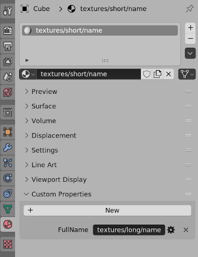
-
I have seen this addon mentioned on the idtech 4 discord regarding exporting doom 3 brushes from blender in the .map format which might let you accomplish some of what you want as far as building level geometry in blender. Haven’t tested it personally for tdm: https://github.com/c-d-a/io_export_qmap
-

Fan Mission: Seeking Lady Leicester, by Grayman (3/21/2023)
Tarhiel replied to Amadeus's topic in Fan Missions
Okay, I had no idea, I have googled it up now and you are right, to my own surprise. Done, I´ve put some paragraphs which were previously not in spoiler tags into spoilers. -

Fan Mission: Seeking Lady Leicester, by Grayman (3/21/2023)
Amadeus replied to Amadeus's topic in Fan Missions
Thebigh is right. The pronunciation tripped me up too, but that is apparently how Leicester is pronounced. Also @TarhielI'm glad you are loving the FM but do you mind putting spoiler tags on your post please -
Suggestion: Phase out long material names (or use an ID system)
R Soul replied to R Soul's topic in The Dark Mod
Something could be done. A few years ago I wrote an addon that looks at a Blender material's diffuse texture and scans the .mtr files to work out the TDM material name. Any name over 63 chars long gets saved in a custom property called FullName. An export script could look in there and do a swap. It's worth noting that my addon is not linked to any export process. Any user can make their own custom properties. I think OrbWeaver did some unrelated modifications to some of the import/export scripts, but it's been a very long time since I've been here so I don't know the current state of that side of things. -
Exporting ASE mesh as CM collision model ?
nbohr1more replied to motorsep's topic in DarkRadiant Feedback and Development
https://wiki.thedarkmod.com/index.php?title=Collision_Models https://wiki.thedarkmod.com/index.php?title=Clipmodel and what is an example of a TDM CM? That is what DMAP produces. It is a map-wide representation of collision. It is not a "model". ( hence all the brush references in the text ) Look again: barrel01_cm.lwo is a typical collision model in TDM. It is a Lightwave object. ( LWO ). If you know of a single editor program that manipulates Doom 3 DMAP collision products ( cm files ) I would be happy to hear of it. -
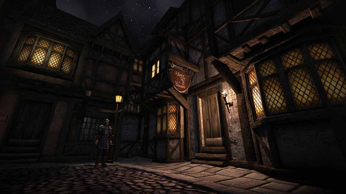
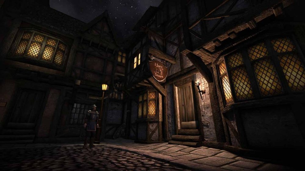
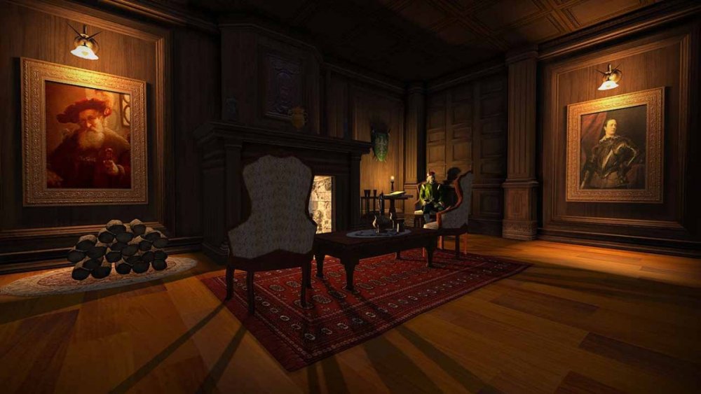
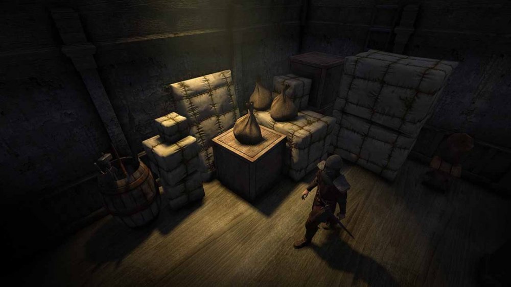
I am pleased to announce the release of our new fan mission, The Hare in the Snare: Part 1 Mission type: City Missions + Inn/Tavern Description: People are being abducted off the streets and a Watch Captain requires the services of a thief to help him find out why. Download link (v1.0.2-release): https://drive.google.com/file/d/1HYvM_u56wDB16uIlb7qgS_q3P24V69MO/view?usp=sharing Credits: Mapping and original characters: @Frost_Salamander Story, readables, custom models, voices and cinematics: @Kerry000 Menu title track produced and mixed by @JackFarmer with selected gigagooga sound samples Beta testers: @Cambridge Spy @Zerg Rush @Amadeus @Acolytesix @Lzocast @wesp5 @nbohr1more @Kerry000 @ate0ate @Wellingtoncrab @prjames Additional thanks: @Dragofer, @nbohr1moreand @peter_spyfor technical help @Springheel for the modules and tutorials @kingsalfor allowing @Kerry000to abuse his manbeast everyone else on Discord and the TDM forums who offered assistance Requirements and notes: This mission requires TDM 2.09. Earlier versions will probably work but you might see one or two missing models. You may experience some FPS drops in some areas with lower-end hardware. Mid-range and above should be fine. If you have issues, I highly recommend you use shadow maps instead of stencil (settings -> advanced -> shadows implementation). It makes a big difference. For 'Hard' and 'Expert' the light gem sensitivity has been increased by '1' (meaning easier for AI to detect you). Screenshots:
- 98 replies
-
- 20
-
-
-
Fan Mission: Seeking Lady Leicester, by Grayman (3/21/2023)
Amadeus replied to Amadeus's topic in Fan Missions
We will look at some of this stuff, but SPOILER tags, please!!! -
Fan Mission: Seeking Lady Leicester, by Grayman (3/21/2023)
Wellingtoncrab replied to Amadeus's topic in Fan Missions
This may make sense in that the performance impact of the volumetric effect can scale with how much of the effect is filling the screen. We shipped with a “performance mode” but had to setup the entities by hand to do it (so it’s not perfect). If you change the LOD detail settings to “Low” or “Lowest” this will disable certain lights, particles and such that can be very heavy to render. You can try these settings and see if you notice an improvement. If not sending us some pictures of heavy areas (with spoiler tags please) will be helpful with tuning these “performance modes” in subsequent patches. Thanks for playing! -
Actually I might be confusing two different things. What the latest LWO exporter fixes is the smoothing angle. Previously this was hard-coded at some weird value slightly less than 90°, but this can now be configured to smooth everything, smooth nothing, or use the Autosmooth Angle setting on the object. I have no idea if explicit smooth groups are supported, or if this is even a thing in Blender.
-
 Is it possible to export ASE mesh as CM collision model (and then somehow view it to visually confirm if it's good or not) ? If I select my model and then go to File > Export Selected as Collision Model, I get model selection dialog window popping up and when I select model there and hit Ok, nothing happens (window closes and I am back in the Editor). No .cm file gets saved.
 -
I'd like to better understand what you want. The design of dragging bodies is to hold frob (key down) to drag and release frob (key up) to let go. That way it's impossible to walk away while unintentionally dragging a body. Plus, it's quick to grab and move several body limbs in rapid succession. This is thought to provide a better experience, especially for new players. Towards the beginning of this thread, I created a "tdm_frobhold_drag_body_behavior" cvar. https://forums.thedarkmod.com/index.php?/topic/22198-feature-proposal-frob-to-use-world-item/&do=findComment&comment=487580 "tdm_frobhold_drag_body_behavior", default:"1" Which drag body behavior? 1 --- on frob key up, drop body (limb). 0 --- on second frob, drop body (limb), TDM v2.11 (and prior) behavior. That cvar was removed shortly afterwards, because it was said that it wasn't needed. With that cvar set to 0, a second frob would be required to let go of the body. Is that the behavior that you want? If so, I can add that cvar back. Also, I saw elsewhere that you want the ability to revert back to the old way. If you mean that all of the controls match TDM 2.11, that can be done with "tdm_frobhold_delay 0" and there will be a menu setting to disable it as well.
-
Exporting ASE mesh as CM collision model ?
HMart replied to motorsep's topic in DarkRadiant Feedback and Development
Solid 1, if no collision surface is available, will use the model geometry itself for collisions (search for combat model in the code also), so yes is not the best approach, doing a custom collision model is always preferable for performance, but doing it on DR is something I personally don't do and IMO is at most, best for simple box like collision models. Like I said the best is to create the collision surfaces in a 3D Tool like blender, you can use the shadow model for it, just change the material from "shadow" to "collision" or even the lower poly LOD model, can't be easier. Btw isn't AFEntity for ragdool physics? I thought that was only for skinned MD5 models not static ASE or LWO models. -
Exporting ASE mesh as CM collision model ?
nbohr1more replied to motorsep's topic in DarkRadiant Feedback and Development
There is no need to "export" a model as a "model". You can export a model as a different model format if desired but there is no logic to it. The model is already in optimized form and ready to be re-textured with collision textures.