Search the Community
Searched results for '/tags/forums/texture/' or tags 'forums/texture/q=/tags/forums/texture/&'.
-
Can DR be used with engines like Godot?
Skaruts replied to Skaruts's topic in DarkRadiant Feedback and Development
@OrbWeaverdo you think you could point me to the part of the code where vertex manipulation is handled? Maybe by looking at it I could figure out how the texture shifting is calculated as a consequence of moving vertices around. -
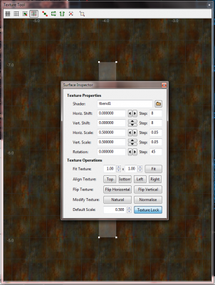
Hello, I want to discuss DR's texture tool and the way Radiant handles texture mapping in this topic. The texture tool is a window (Ctrl+Alt+T) where you can fine tune how a given texture gets mapped on a brush's face. I have noticed that, oftentimes when selecting multiple sides of a brush, the unwrapped UV islands are placed way too far from each other. Not something you'd care about during regular mapping, but I think this is a problem in theory, which can become a problem in practice when exporting models from DR. This is actually my impetus for starting this thread, as I imported a DR model in Blender only to find its UV map being all over the place. Here is an example of what I consider problematic. You can see that the face I've selected, behind the Surface Inspector, is already in the negative quadrant of the UV coord grid. Yet the surface inspector shows both horiz. and vert. shift to be at 0. Moreover, if I start changing those values with the arrow keys, the shifts will go up to 255 and then wrap back to zero, while the UV map will continue to scroll through the UV grid infinitely, instead of looping back to where it was. Couple this with the arcane way in which the Paste Shader commands work, and you have situations where two brush faces might look aligned in 3D but have their UV maps be thousands of units apart in 2D. Is there an explanation for why this works the way it does? Any way to make it better? Obviously, I'm not asking for DR to magically clamp all UV maps to the 0-1 UV space or unwrap brushes' sides like a modelling app would. It does, however, seem weird why there'd no apparent anchor for mapping faces to the UV space and they keep straying from the origin constantly.
-
You can start here: https://forums.thedarkmod.com/index.php?/topic/12558-useful-important-editing-links/ Specifically, I recommend Springheel's new mapper's workshop: https://forums.thedarkmod.com/index.php?/topic/18945-tdm-new-mappers-workshop/
-
Isn't this the method described in this wiki tutorial? https://wiki.thedarkmod.com/index.php?title=Full-Screen_Video_Cutscenes#Movie_Theatre_Method_2 This seems like a video as a texture on a surface.
-

Should we consider using detail textures?
MirceaKitsune replied to MirceaKitsune's topic in The Dark Mod
Megatextures were a horrible idea for obvious reasons, not sure why ID chose to learn that the hard way. The concept from what I remember is the whole map uses a single gigantic texture... instead of how we independently pick a couple of 1024 px brick materials for a few brushes and surfaces, the whole map acts as one model with one material and a single texture which probably needs to be 1 million x 1 million pixels even for a small level. This is ridiculous from a perspective of system resources with 100's of GB's of storage and huge (v)RAM requirements and hours of loading time, as well as raising the skills required for level editing since you now need mappers to also be texture artists and sculpt / paint their levels instead of just placing stuff. The only thinkable benefit is there's no repetition since every pixel on every part of the world is unique, but who notices any similarity with independent texturing if it's done right anyway? Detail textures have yet another advantage there: Since you scale the pattern independently on top of the original texture, you can make every surface appear as if it has unique pixels like megatextures. Hence why I'd advice having the details be very high-res, 4k or 8k even 16k if we can take it: Yes that's enormous, but remember we'd only have a few patterns probably no more than 15 in total, and can store them as grayscale then use a single image to modify both albedo / specular / normal (heightmap to normalmap): Map the detail in world space rather than the brush or model UV map, and the resulting pattern on every surface in the world will always be unique since the original and detail textures will be out of sync. -
Hi, I need to know what the code is to use Spoiler Tags. I am using my tablet and I don't have the options to use anything, like spoiler tags, quote tags, text changes etc. Thanks
-
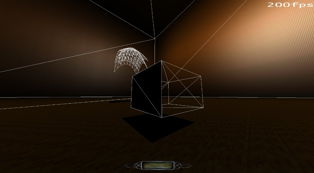
 EDIT: EVGA 980ti on latest drivers, if that matters. I've been plugging away at my cave map, but I keep running into issues so it's taking a long time. Now, the skybox isn't working. Basically the sky texture is just transparent. I fixed it by deleting the brushes, creating new ones and texturing just one face as sky. After DMAP that worked. So I then textured the other 3 sides and then it was broken again. Changing the other 3 sides back to regular textures didn't fix the broken sky rendering. Now, even deleting the skybox prefab, the offending textures/brushes etc, won't fix it. I created a test map, and copied and pasted the same brushes and prefab and it's also broken there. Deleting the prefab and readding it, and texturing new brushes with sky, won't work. In 2.08: In SVN: You can see the prefab is very close to the sky texture. I've also tried moving the skybox prefab outside the map and at various places, even to 0,0,0 but that didn't help. The skybox looks fine in game, I can noclip into it and see all the little details. I've attached the map file, you'll have to rename the file from maps.zip.txt to maps.zip to extract it. skytest.zip
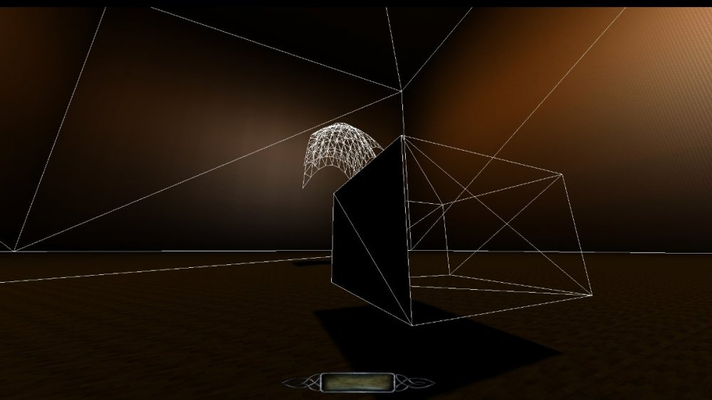

-
 This issue has been occurring in the last few weeks, and my first thought was that it is due to a regression that happened during the code reorganisation and the necessary changes to GL context handling. In my Ubuntu 20.10 machine I walked back the git history up to the point of the DR 2.8.0 release, but as it turns out, the problem is happening there too. When switching between Media and Texture tabs, the GL widget is not refreshed, unless you resize the tabs using the splitter between cam and orthoview: So I launched my other VM running Ubuntu 19.10 and was rather surprised that this problem does not happen there, even with the latest git checkout: I'm not sure where this behaviour is coming from all of a sudden. While I can't rule out that DR is doing something wrong in terms of context handling, there sure seems to be a difference between the two Ubuntu 19/20 setups. Any suggestions on how to go ahead and find out where the problem is rooted? The one idea I have: Since Ubuntu 19 is using wxGTK 3.0.4 and Ubuntu 20 is using the latest wxGTK 3.0.5, I will try to compile the older wxWidgets 3.0.4 release from source and use that in the newer Ubuntu 20 version, to see if the problem goes away.
-
Not so long ago I found what could make a pretty good profile picture and decided to try it out on these new forums. But I couldn't find a button anywhere that would let me change it. I asked on Discord and it seems Spooks also couldn't find anything anywhere. So I logged into an old alternative account and, lo and behold, that account has a button. This is on the first screen I get when I: 1) click on my account name in the top-right of the browser -> 2) click on 'profile'. Compared to my actual account: Are you also missing this button on your account? It'd be very much appreciated if that functionality could be restored to any of the affected accounts.
-
If like me you scour the web looking for inspiration for your next TDM mission then look no further.. Now... talking of images have you guys seen the latest from the master that is DrK from his Rocksbourg4 campaign. We need more dirty texture in TDM me thinks...
-
A couple more: https://forums.thedarkmod.com/index.php?/topic/21739-resolved-allow-mantling-while-carrying-a-body/ https://forums.thedarkmod.com/index.php?/topic/22211-feature-proposal-new-lean-for-tdm-212/ https://forums.thedarkmod.com/index.php?/topic/22198-feature-proposal-frob-to-use-world-item/ https://forums.thedarkmod.com/index.php?/topic/22249-212-auto-search-bodies/
-
the code pieces that needs modifying are these -> /* ================== RB_GLSL_DrawInteraction ================== */ static void RB_GLSL_DrawInteraction( const drawInteraction_t *din ) { /* Half Lambertian constants */ static const float whalf[] = { 0.0f, 0.0f, 0.0f, 0.5f }; static const float wzero[] = { 0.0f, 0.0f, 0.0f, 0.0f }; static const float wone[] = { 0.0f, 0.0f, 0.0f, 1.0f }; // load all the vertex program parameters qglUniform4fv( u_light_origin, 1, din->localLightOrigin.ToFloatPtr() ); qglUniform4fv( u_view_origin, 1, din->localViewOrigin.ToFloatPtr() ); qglUniformMatrix2x4fv( u_diffMatrix, 1, GL_FALSE, RB_GLSL_MakeMatrix( DIFFMATRIX( 0 ), DIFFMATRIX( 1 ) ) ); qglUniformMatrix2x4fv( u_bumpMatrix, 1, GL_FALSE, RB_GLSL_MakeMatrix( BUMPMATRIX( 0 ), BUMPMATRIX( 1 ) ) ); qglUniformMatrix2x4fv( u_specMatrix, 1, GL_FALSE, RB_GLSL_MakeMatrix( SPECMATRIX( 0 ), SPECMATRIX( 1 ) ) ); qglUniformMatrix4fv( u_projMatrix, 1, GL_FALSE, RB_GLSL_MakeMatrix( PROJMATRIX( 0 ), PROJMATRIX( 1 ), wzero, PROJMATRIX( 2 ) ) ); qglUniformMatrix4fv( u_fallMatrix, 1, GL_FALSE, RB_GLSL_MakeMatrix( PROJMATRIX( 3 ), whalf, wzero, wone ) ); /* Lambertian constants */ static const float zero[4] = { 0.0f, 0.0f, 0.0f, 0.0f }; static const float one[4] = { 1.0f, 1.0f, 1.0f, 1.0f }; static const float negOne[4] = { -1.0f, -1.0f, -1.0f, -1.0f }; switch ( din->vertexColor ) { case SVC_IGNORE: qglUniform4fv( u_color_modulate, 1, zero ); qglUniform4fv( u_color_add, 1, one ); break; case SVC_MODULATE: qglUniform4fv( u_color_modulate, 1, one ); qglUniform4fv( u_color_add, 1, zero ); break; case SVC_INVERSE_MODULATE: qglUniform4fv( u_color_modulate, 1, negOne ); qglUniform4fv( u_color_add, 1, one ); break; } // set the constant colors qglUniform4fv( u_constant_diffuse, 1, din->diffuseColor.ToFloatPtr() ); qglUniform4fv( u_constant_specular, 1, din->specularColor.ToFloatPtr() ); // TODO: shader gamma for GLSL. // set the textures RB_ARB2_BindInteractionTextureSet( din ); // draw it RB_DrawElementsWithCounters( din->surf->geo ); } /* ================== RB_ARB2_DrawInteraction ================== */ static void RB_ARB2_DrawInteraction( const drawInteraction_t *din ) { // load all the vertex program parameters qglProgramEnvParameter4fvARB( GL_VERTEX_PROGRAM_ARB, PP_LIGHT_ORIGIN, din->localLightOrigin.ToFloatPtr() ); qglProgramEnvParameter4fvARB( GL_VERTEX_PROGRAM_ARB, PP_VIEW_ORIGIN, din->localViewOrigin.ToFloatPtr() ); qglProgramEnvParameter4fvARB( GL_VERTEX_PROGRAM_ARB, PP_LIGHT_PROJECT_S, din->lightProjection[0].ToFloatPtr() ); qglProgramEnvParameter4fvARB( GL_VERTEX_PROGRAM_ARB, PP_LIGHT_PROJECT_T, din->lightProjection[1].ToFloatPtr() ); qglProgramEnvParameter4fvARB( GL_VERTEX_PROGRAM_ARB, PP_LIGHT_PROJECT_Q, din->lightProjection[2].ToFloatPtr() ); qglProgramEnvParameter4fvARB( GL_VERTEX_PROGRAM_ARB, PP_LIGHT_FALLOFF_S, din->lightProjection[3].ToFloatPtr() ); qglProgramEnvParameter4fvARB( GL_VERTEX_PROGRAM_ARB, PP_BUMP_MATRIX_S, din->bumpMatrix[0].ToFloatPtr() ); qglProgramEnvParameter4fvARB( GL_VERTEX_PROGRAM_ARB, PP_BUMP_MATRIX_T, din->bumpMatrix[1].ToFloatPtr() ); qglProgramEnvParameter4fvARB( GL_VERTEX_PROGRAM_ARB, PP_DIFFUSE_MATRIX_S, din->diffuseMatrix[0].ToFloatPtr() ); qglProgramEnvParameter4fvARB( GL_VERTEX_PROGRAM_ARB, PP_DIFFUSE_MATRIX_T, din->diffuseMatrix[1].ToFloatPtr() ); qglProgramEnvParameter4fvARB( GL_VERTEX_PROGRAM_ARB, PP_SPECULAR_MATRIX_S, din->specularMatrix[0].ToFloatPtr() ); qglProgramEnvParameter4fvARB( GL_VERTEX_PROGRAM_ARB, PP_SPECULAR_MATRIX_T, din->specularMatrix[1].ToFloatPtr() ); // testing fragment based normal mapping if ( r_testARBProgram.GetBool() ) { qglProgramEnvParameter4fvARB( GL_FRAGMENT_PROGRAM_ARB, 2, din->localLightOrigin.ToFloatPtr() ); qglProgramEnvParameter4fvARB( GL_FRAGMENT_PROGRAM_ARB, 3, din->localViewOrigin.ToFloatPtr() ); } static const float zero[4] = { 0.0f, 0.0f, 0.0f, 0.0f }; static const float one[4] = { 1.0f, 1.0f, 1.0f, 1.0f }; static const float negOne[4] = { -1.0f, -1.0f, -1.0f, -1.0f }; switch ( din->vertexColor ) { case SVC_IGNORE: qglProgramEnvParameter4fvARB( GL_VERTEX_PROGRAM_ARB, PP_COLOR_MODULATE, zero ); qglProgramEnvParameter4fvARB( GL_VERTEX_PROGRAM_ARB, PP_COLOR_ADD, one ); break; case SVC_MODULATE: qglProgramEnvParameter4fvARB( GL_VERTEX_PROGRAM_ARB, PP_COLOR_MODULATE, one ); qglProgramEnvParameter4fvARB( GL_VERTEX_PROGRAM_ARB, PP_COLOR_ADD, zero ); break; case SVC_INVERSE_MODULATE: qglProgramEnvParameter4fvARB( GL_VERTEX_PROGRAM_ARB, PP_COLOR_MODULATE, negOne ); qglProgramEnvParameter4fvARB( GL_VERTEX_PROGRAM_ARB, PP_COLOR_ADD, one ); break; } // set the constant colors qglProgramEnvParameter4fvARB( GL_FRAGMENT_PROGRAM_ARB, 0, din->diffuseColor.ToFloatPtr() ); qglProgramEnvParameter4fvARB( GL_FRAGMENT_PROGRAM_ARB, 1, din->specularColor.ToFloatPtr() ); // DG: brightness and gamma in shader as program.env[4] if ( r_gammaInShader.GetBool() ) { // program.env[4].xyz are all r_brightness, program.env[4].w is 1.0f / r_gamma float parm[4]; parm[0] = parm[1] = parm[2] = r_brightness.GetFloat(); parm[3] = 1.0f / r_gamma.GetFloat(); // 1.0f / gamma so the shader doesn't have to do this calculation qglProgramEnvParameter4fvARB( GL_FRAGMENT_PROGRAM_ARB, PP_GAMMA_BRIGHTNESS, parm ); } // set the textures RB_ARB2_BindInteractionTextureSet( din ); // draw it RB_DrawElementsWithCounters( din->surf->geo ); } i left in the arb version so you can get an idea of what is going on, also this piece -> /* ================= R_LoadARBProgram ================= */ void R_LoadARBProgram( int progIndex ) { int ofs; int err; char *buffer; char *start = NULL, *end; #if D3_INTEGRATE_SOFTPART_SHADERS if ( progs[progIndex].ident == VPROG_SOFT_PARTICLE || progs[progIndex].ident == FPROG_SOFT_PARTICLE ) { // these shaders are loaded directly from a string common->Printf( "<internal> %s", progs[progIndex].name ); const char *srcstr = ( progs[progIndex].ident == VPROG_SOFT_PARTICLE ) ? softpartVShader : softpartFShader; // copy to stack memory buffer = ( char * )_alloca( strlen( srcstr ) + 1 ); strcpy( buffer, srcstr ); } else #endif // D3_INTEGRATE_SOFTPART_SHADERS { idStr fullPath = "glprogs/"; fullPath += progs[progIndex].name; char *fileBuffer; common->Printf( "%s", fullPath.c_str() ); // load the program even if we don't support it, so // fs_copyfiles can generate cross-platform data dumps fileSystem->ReadFile( fullPath.c_str(), ( void ** )&fileBuffer, NULL ); if ( !fileBuffer ) { common->Printf( ": File not found\n" ); return; } // copy to stack memory and free buffer = ( char * )_alloca( strlen( fileBuffer ) + 1 ); strcpy( buffer, fileBuffer ); fileSystem->FreeFile( fileBuffer ); } if ( !glConfig.isInitialized ) { return; } // // submit the program string at start to GL // if ( progs[progIndex].ident == 0 ) { // allocate a new identifier for this program progs[progIndex].ident = PROG_USER + progIndex; } // vertex and fragment programs can both be present in a single file, so // scan for the proper header to be the start point, and stamp a 0 in after the end if ( progs[progIndex].target == GL_VERTEX_PROGRAM_ARB ) { if ( !glConfig.ARBVertexProgramAvailable ) { common->Printf( ": GL_VERTEX_PROGRAM_ARB not available\n" ); return; } start = strstr( buffer, "!!ARBvp" ); } if ( progs[progIndex].target == GL_FRAGMENT_PROGRAM_ARB ) { if ( !glConfig.ARBFragmentProgramAvailable ) { common->Printf( ": GL_FRAGMENT_PROGRAM_ARB not available\n" ); return; } start = strstr( buffer, "!!ARBfp" ); } if ( !start ) { common->Printf( ": !!ARB not found\n" ); return; } end = strstr( start, "END" ); if ( !end ) { common->Printf( ": END not found\n" ); return; } end[3] = 0; // DG: hack gamma correction into shader. TODO shader gamma for GLSL if ( r_gammaInShader.GetBool() && progs[progIndex].target == GL_FRAGMENT_PROGRAM_ARB && strstr( start, "nodhewm3gammahack" ) == NULL ) { // note that strlen("dhewm3tmpres") == strlen("result.color") const char *tmpres = "TEMP dhewm3tmpres; # injected by dhewm3 for gamma correction\n"; // Note: program.env[21].xyz = r_brightness; program.env[21].w = 1.0/r_gamma // outColor.rgb = pow(dhewm3tmpres.rgb*r_brightness, vec3(1.0/r_gamma)) // outColor.a = dhewm3tmpres.a; const char *extraLines = "# gamma correction in shader, injected by dhewm3\n" // MUL_SAT clamps the result to [0, 1] - it must not be negative because // POW might not work with a negative base (it looks wrong with intel's Linux driver) // and clamping values > 1 to 1 is ok because when writing to result.color // it's clamped anyway and pow(base, exp) is always >= 1 for base >= 1 "MUL_SAT dhewm3tmpres.xyz, program.env[21], dhewm3tmpres;\n" // first multiply with brightness "POW result.color.x, dhewm3tmpres.x, program.env[21].w;\n" // then do pow(dhewm3tmpres.xyz, vec3(1/gamma)) "POW result.color.y, dhewm3tmpres.y, program.env[21].w;\n" // (apparently POW only supports scalars, not whole vectors) "POW result.color.z, dhewm3tmpres.z, program.env[21].w;\n" "MOV result.color.w, dhewm3tmpres.w;\n" // alpha remains unmodified "\nEND\n\n"; // we add this block right at the end, replacing the original "END" string int fullLen = strlen( start ) + strlen( tmpres ) + strlen( extraLines ); char *outStr = ( char * )_alloca( fullLen + 1 ); // add tmpres right after OPTION line (if any) char *insertPos = R_FindArbShaderComment( start, "OPTION" ); if ( insertPos == NULL ) { // no OPTION? then just put it after the first line (usually something like "!!ARBfp1.0\n") insertPos = start; } // but we want the position *after* that line while ( *insertPos != '\0' && *insertPos != '\n' && *insertPos != '\r' ) { ++insertPos; } // skip the newline character(s) as well while ( *insertPos == '\n' || *insertPos == '\r' ) { ++insertPos; } // copy text up to insertPos int curLen = insertPos - start; memcpy( outStr, start, curLen ); // copy tmpres ("TEMP dhewm3tmpres; # ..") memcpy( outStr + curLen, tmpres, strlen( tmpres ) ); curLen += strlen( tmpres ); // copy remaining original shader up to (excluding) "END" int remLen = end - insertPos; memcpy( outStr + curLen, insertPos, remLen ); curLen += remLen; outStr[curLen] = '\0'; // make sure it's NULL-terminated so normal string functions work // replace all existing occurrences of "result.color" with "dhewm3tmpres" for ( char *resCol = strstr( outStr, "result.color" ); resCol != NULL; resCol = strstr( resCol + 13, "result.color" ) ) { memcpy( resCol, "dhewm3tmpres", 12 ); // both strings have the same length. // if this was part of "OUTPUT bla = result.color;", replace // "OUTPUT bla" with "ALIAS bla" (so it becomes "ALIAS bla = dhewm3tmpres;") char *s = resCol - 1; // first skip whitespace before "result.color" while ( s > outStr && ( *s == ' ' || *s == '\t' ) ) { --s; } // if there's no '=' before result.color, this line can't be affected if ( *s != '=' || s <= outStr + 8 ) { continue; // go on with next "result.color" in the for-loop } --s; // we were on '=', so go to the char before and it's time to skip whitespace again while ( s > outStr && ( *s == ' ' || *s == '\t' ) ) { --s; } // now we should be at the end of "bla" (or however the variable/alias is called) if ( s <= outStr + 7 || !R_IsArbIdentifier( *s ) ) { continue; } --s; // skip all the remaining chars that are legal in identifiers while ( s > outStr && R_IsArbIdentifier( *s ) ) { --s; } // there should be at least one space/tab between "OUTPUT" and "bla" if ( s <= outStr + 6 || ( *s != ' ' && *s != '\t' ) ) { continue; } --s; // skip remaining whitespace (if any) while ( s > outStr && ( *s == ' ' || *s == '\t' ) ) { --s; } // now we should be at "OUTPUT" (specifically at its last 'T'), // if this is indeed such a case if ( s <= outStr + 5 || *s != 'T' ) { continue; } s -= 5; // skip to start of "OUTPUT", if this is indeed "OUTPUT" if ( idStr::Cmpn( s, "OUTPUT", 6 ) == 0 ) { // it really is "OUTPUT" => replace "OUTPUT" with "ALIAS " memcpy( s, "ALIAS ", 6 ); } } assert( curLen + strlen( extraLines ) <= fullLen ); // now add extraLines that calculate and set a gamma-corrected result.color // strcat() should be safe because fullLen was calculated taking all parts into account strcat( outStr, extraLines ); start = outStr; } qglBindProgramARB( progs[progIndex].target, progs[progIndex].ident ); qglGetError(); qglProgramStringARB( progs[progIndex].target, GL_PROGRAM_FORMAT_ASCII_ARB, strlen( start ), start ); err = qglGetError(); qglGetIntegerv( GL_PROGRAM_ERROR_POSITION_ARB, ( GLint * )&ofs ); if ( err == GL_INVALID_OPERATION ) { const GLubyte *str = qglGetString( GL_PROGRAM_ERROR_STRING_ARB ); common->Printf( "\nGL_PROGRAM_ERROR_STRING_ARB: %s\n", str ); if ( ofs < 0 ) { common->Printf( "GL_PROGRAM_ERROR_POSITION_ARB < 0 with error\n" ); } else if ( ofs >= ( int )strlen( start ) ) { common->Printf( "error at end of program\n" ); } else { int printOfs = Max( ofs - 20, 0 ); // DG: print some more context common->Printf( "error at %i:\n%s", ofs, start + printOfs ); } return; } if ( ofs != -1 ) { common->Printf( "\nGL_PROGRAM_ERROR_POSITION_ARB != -1 without error\n" ); return; } common->Printf( "\n" ); } in draw_arb2.cpp and /* ================== RB_SetProgramEnvironment Sets variables that can be used by all vertex programs [SteveL #3877] Note on the use of fragment program environmental variables. Parameters 0 and 1 are set here to allow conversion of screen coordinates to texture coordinates, for use when sampling _currentRender. Those same parameters 0 and 1, plus 2 and 3, are given entirely different meanings in draw_arb2.cpp while light interactions are being drawn. This function is called again before currentRender size is needed by post processing effects are done, so there's no clash. Only parameters 0..3 were in use before #3877 - and in dhewm3 also 4, for gamma in shader. Now I've used a new parameter 22 for the size of _currentDepth. It's needed throughout, including by light interactions, and its size might in theory differ from _currentRender. Parameters 23 and 24 are used by soft particles #3878. Note these can be freely reused by different draw calls. ================== */ void RB_SetProgramEnvironment( bool isPostProcess ) { float parm[4]; int pot; if ( !glConfig.ARBVertexProgramAvailable ) { return; } #if 0 // screen power of two correction factor, one pixel in so we don't get a bilerp // of an uncopied pixel int w = backEnd.viewDef->viewport.x2 - backEnd.viewDef->viewport.x1 + 1; pot = globalImages->currentRenderImage->uploadWidth; if ( w == pot ) { parm[0] = 1.0; } else { parm[0] = ( float )( w - 1 ) / pot; } int h = backEnd.viewDef->viewport.y2 - backEnd.viewDef->viewport.y1 + 1; pot = globalImages->currentRenderImage->uploadHeight; if ( h == pot ) { parm[1] = 1.0; } else { parm[1] = ( float )( h - 1 ) / pot; } parm[2] = 0; parm[3] = 1; qglProgramEnvParameter4fvARB( GL_VERTEX_PROGRAM_ARB, 0, parm ); #else // screen power of two correction factor, assuming the copy to _currentRender // also copied an extra row and column for the bilerp int w = backEnd.viewDef->viewport.x2 - backEnd.viewDef->viewport.x1 + 1; pot = globalImages->currentRenderImage->uploadWidth; parm[0] = ( float )w / pot; int h = backEnd.viewDef->viewport.y2 - backEnd.viewDef->viewport.y1 + 1; pot = globalImages->currentRenderImage->uploadHeight; parm[1] = ( float )h / pot; parm[2] = 0; parm[3] = 1; qglProgramEnvParameter4fvARB( GL_VERTEX_PROGRAM_ARB, 0, parm ); #endif qglProgramEnvParameter4fvARB( GL_FRAGMENT_PROGRAM_ARB, 0, parm ); // window coord to 0.0 to 1.0 conversion parm[0] = 1.0 / w; parm[1] = 1.0 / h; parm[2] = 0; parm[3] = 1; qglProgramEnvParameter4fvARB( GL_FRAGMENT_PROGRAM_ARB, 1, parm ); // DG: brightness and gamma in shader as program.env[4]. TODO: shader gamma for GLSL if ( r_gammaInShader.GetBool() ) { // program.env[4].xyz are all r_brightness, program.env[4].w is 1.0/r_gamma if ( !isPostProcess ) { parm[0] = parm[1] = parm[2] = r_brightness.GetFloat(); parm[3] = 1.0f / r_gamma.GetFloat(); // 1.0f / gamma so the shader doesn't have to do this calculation } else { // don't apply gamma/brightness in postprocess passes to avoid applying them twice // (setting them to 1.0 makes them no-ops) parm[0] = parm[1] = parm[2] = parm[3] = 1.0f; } qglProgramEnvParameter4fvARB( GL_FRAGMENT_PROGRAM_ARB, PP_GAMMA_BRIGHTNESS, parm ); } // #3877: Allow shaders to access depth buffer. // Two useful ratios are packed into this parm: [0] and [1] hold the x,y multipliers you need to map a screen // coordinate (fragment position) to the depth image: those are simply the reciprocal of the depth // image size, which has been rounded up to a power of two. Slots [3] and [4] hold the ratio of the depth image // size to the current render image size. These sizes can differ if the game crops the render viewport temporarily // during post-processing effects. The depth render is smaller during the effect too, but the depth image doesn't // need to be downsized, whereas the current render image does get downsized when it's captured by the game after // the skybox render pass. The ratio is needed to map between the two render images. parm[0] = 1.0f / globalImages->currentDepthImage->uploadWidth; parm[1] = 1.0f / globalImages->currentDepthImage->uploadHeight; parm[2] = static_cast<float>( globalImages->currentRenderImage->uploadWidth ) / globalImages->currentDepthImage->uploadWidth; parm[3] = static_cast<float>( globalImages->currentRenderImage->uploadHeight ) / globalImages->currentDepthImage->uploadHeight; qglProgramEnvParameter4fvARB( GL_FRAGMENT_PROGRAM_ARB, PP_CURDEPTH_RECIPR, parm ); // // set eye position in global space // parm[0] = backEnd.viewDef->renderView.vieworg[0]; parm[1] = backEnd.viewDef->renderView.vieworg[1]; parm[2] = backEnd.viewDef->renderView.vieworg[2]; parm[3] = 1.0; qglProgramEnvParameter4fvARB( GL_VERTEX_PROGRAM_ARB, 1, parm ); } in draw_common.cpp. note the TODO sections. biggest problem right now is probably in R_LoadARBProgram which is not used by the GLSL backend at all since it only handles the interaction shaders atm. it does have its own version of this function but it is lobotomized and only used if for some reason a user wants to use an external shader.it is here in draw_arb2.cpp -> /* ================== GL_GetGLSLFromFile ================== */ static GLchar *GL_GetGLSLFromFile( GLchar *name ) { idStr fullPath = "glprogs130/"; fullPath += name; GLchar *fileBuffer; GLchar *buffer; if ( !glConfig.isInitialized ) { return NULL; } fileSystem->ReadFile( fullPath.c_str(), reinterpret_cast<void **>( &fileBuffer ), NULL ); if ( !fileBuffer ) { common->Printf( "%s: File not found, using internal shaders\n", fullPath.c_str() ); return NULL; } // copy to stack memory (do not use _alloca here!!! it breaks loading the shaders) buffer = reinterpret_cast<GLchar *>( Mem_Alloc( strlen( fileBuffer ) + 1 ) ); strcpy( buffer, fileBuffer ); fileSystem->FreeFile( fileBuffer ); common->Printf( "%s: loaded\n", fullPath.c_str() ); return buffer; } as you can see it is somewhat more empty than the arb shaders version, but would probably suffice for the same thing.
-
ok so after getting myself a rtx 3070 im left with a bit of a wonder about all the fud on the net. elitist users claim the 3070 cant do 4k (debunked it handles 4k just fine but you need to lower the texture resolution in some titles to not overshoot the frankly rather low amount of vram -> 8 gb). some back and forth on the 2080ti some claim that the 3070 is faster while others claim the 2080ti is. (from my own experience the 2080ti is a bit faster in 4k while the 3070 is a bit faster in lower resolutions). if you play exclusively in 4k go for the 2080ti -> reason it has more vram 11gb vs 8gb this might not sound like a huge deal but the extra 3gb helps a lot with ultra high texture resolutions. debunked (claims that the 3070 uses newer dlss features, it does not. the 2080ti supports the exact same dlss features that the 3070 does, it even supports dlss 3 minus the framegen feature. some claims the 3070 uses newer tensor cores which are faster, well is they are i dont see it... the 2080 ti has 4 times the amount of tensor cores compared to the 3070 while the 3070 has around 1000 more cuda cores hmm ???). the real reason i think the 3070 got so popular is that it delivered close to the same performance of the insanely overpriced 2080ti, i cant fault people for that choice but i would like some realism in the comparison and not something based on just the price. the 2080ti was a highend card back when it was new while the 3070 is a mid range card at half the price of the 2080ti with at least comparable performance but lacks enough vram to play all titles at 4k with everything cranked to the max. playing hzd forbidden west on the 3070 atm in 4k with everything on max except texture resolution which i have on high and i get > 80 fps with the framegen mod and around 45 fps without it (dlss is flaky in this game though), the 2080ti in the same game in 4k gets around 100 fps with the framegen mod and 55 fps without it with texture resolution at the highest setting).
-
 This is something I had in mind a while back. To me, both names and usage of those tabs is kind of overlapping and confusing, especially to newcomers. First off, the naming convention. Media tab lists all available material shaders (and not any other media, like sound shaders), while Textures tab is a list of material shaders currently used in the map. Not only the tab names are technically wrong, but also the functionalities could be merged into one tab, I think. If you ever worked in other engines, a typical content/material browser does load all materials used in current map, but it also has a folder structure list on the left hand side (this would be the equivalent of Media tab). Double clicking a package name loads the material and displays its preview tile in the pane on the right hand side. To achieve similar functionality, I imagine the Media and Textures tabs would have to be merged into one Materials tab. I only have doubts about having it as a embedded window in Regular or Regular Left window layout (i.e. under the perspective view and sharing its width lock with it). Having it as separate floating window, as with other inspectors, would probably work better. In general, this should speed up mappers work and make the use of materials more intuitive (I hope). Your thoughts? @greebo, @OrbWeaver are there technical blockers in terms of DR coding? Edit, a mock up:
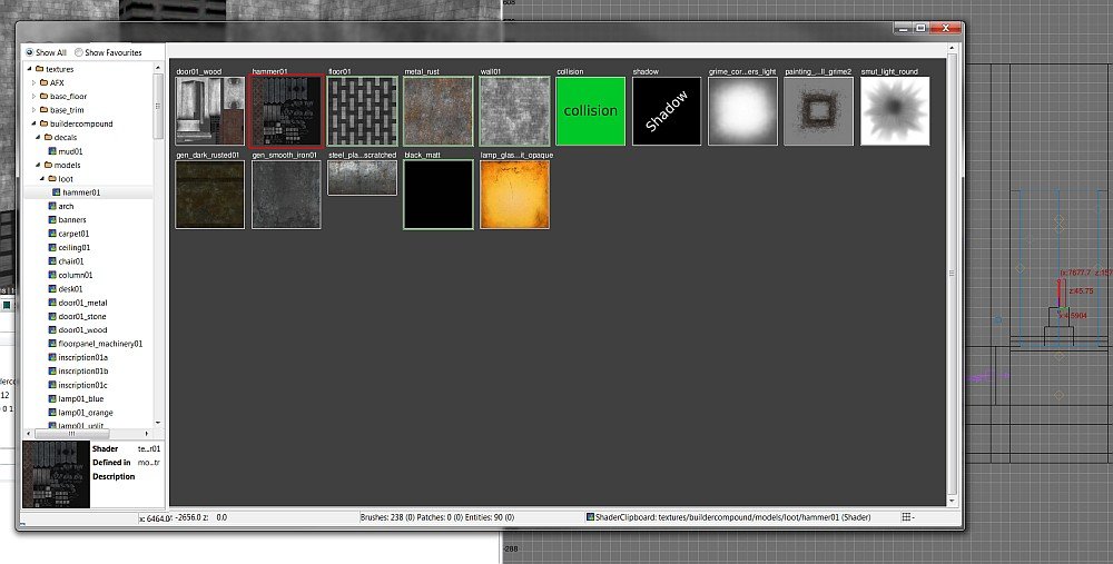
-
Btw. IMO it would be useful to use .dds images in regular myFM/textures folder structure, so you don't have to replicate that in dedicated dds folder. TDM doesn't use texture quality settings anyway, it's a deprecated Doom3 thing.
-
I was wondering if there's a special DarkRadiant technique/tool for adjusting a texture orientation by an edge. A level designer I'm working with made a demo video describing this: Basically, right now he is doing some calculator work to angle a texture along an edge -- is there a shortcut of some kind to do this? Thanks!
-
I remember one case where smoothing groups were a pain to transfer to TDM correctly: And I looked into TDM code which preprocesses LWO models. Of course it usually works fine, but it is not a reliable solution. If you encounter a model which is broken by this import code, you will have to workaround it on your side, either by tweaking the model, or by tweaking the exporter. Also, I believe I saw a large LWO model (terrain) which took a lot of time to load because of this preprocessing. OBJ format is very good because it supports multi-patch texture atlas and smooth groups topologically. There is zero preprocessing on TDM side: you'll get exactly what is written in the OBJ file. And loading large model is much faster despite OBJ being text format. Anyway, if someone wants to maintain a wiki article about the formats, then I think it would be very helpful to list all the working export tools. Names, versions, instructions and forum threads, known caveats, etc.
-
Thanks! I actually changed the light to a Cubic - cubelightCube and used the texture I had made for the ambientCube and that did the trick.
-
Here is what I know: static models: LWO: somewhat default small uncompressed size since it is binary loading code is horrible, can be slow and break your model (smoothing groups might be pain) ASE: larger uncompressed size since it is text (compressed size is probably OK?) loading code is as awful as for LWO OBJ: the only format added specifically for TDM, so not very widespread uncompressed size is large because it is text (compressed size is probably OK?) loading is very fast and does not "fix"/break your model, you'll get exactly the topology & smoothing you exported ragdolls: The only format is .af text format, which is handmade for Doom 3. No changes here since Doom 3. It is notoriously hard to create/edit. The only tool is the Windows-only builtin command editAFs, and this is the only in-game editor which has no outside alternatives. We wanted to port it to either DarkRadiant or at least better GUI framework, but it did not happen. animation: MD5: md5mesh --- Doom 3 custom text format which represents a mesh attached to skeleton (joints, weights, etc.) md5anim --- custom text format that represents an animation of a skeleton. I'm pretty sure Blender has some working exporter for these. MD3: This is Doom 3 custom text format which represents linear vertex morphing. It is rarely used, but it is a perfect fit in case animation is clearly not "skeletal" (e.g. animated grass or water). I suppose some converters can be found?... Ask @Arcturus, he used it. Also there are some hardcoded pieces of code which transform a mesh into something else, that are enabled via "deform" keyword in material. The most known example is particles. All of this is very specific and uses custom formats. There is also MA loader (Maya ascii format?), but it is not used an I have no idea how functional it is. Also there is FLT model, but no idea what it is. video: The mainstream idea is to use (mp4 + h264 + aac) for FMV. There is also legacy support for ROQ, but I guess you should not use it today. I think all the other formats are disabled in FFmpeg build that we use. There is no common understanding about in-game videos, I'm not even sure it is a useful case. One specific case is animated textures (e.g. water), and they are usually implemented as a pack of copy/pasted if-s in material file, which point to different frame images. Something like "Motion JPEG/TGA/PNG/DDS" Maybe one day we will make this approach easier to use... textures and images: TGA: The simplest uncompressed format, basically default in case compression is not used. PNG: Lossless compression, but pretty slow to load. Should be OK for some GUI images, but probably not a good idea to e.g. write all normal maps as PNGs: I imagine loading times will increase noticeably if we do so JPG: Lossy format, but pretty small and rather fast to load. I think it is usually used for screenshots and maybe GUI images, otherwise not popular. DDS: This is container which can in principle store both compressed and uncompressed data, but I think we use it only for precompressed textures. TDM supports DXT1, DXT3, DXT5, RGTC compressed formats (each of these formats has a bunch of pseudonymes). If you use compressed DDS, then you can be sure it will be displayed as is, as no further processing it applied to it. Sometimes it is good, sometimes it is bad. The engine has fast compressor/decompressed for all texture compression formats, so if you supply TGAs and they are compressed on load, you only lose in mission size. Images inside guis (briefing, readables) use the same material loading system, so they should support all the same image formats. sound files: OGG: Relatively widespread open format with lossy compression. I guess it is used for everything by default, which seems OK to me. OGG files are loaded on level start, but decompressed on the fly. WAV: Simple uncompressed sound file. Obviously larger than OGG, not sure why it is used sometimes (maybe less compression artifacts?) The only thing I know is that the "shakes" feature of materials specifically asks for WAV.
-
PLAYERS Implemented new system to estimate light for AI purposes. Players usually try to hide bodies in dark places so that guards don't see it when passing by. However, the old light estimate system does not properly account for shadows, so what is dark for player can be fully bright for AI. The new system considers all the details including: shadows, projected light textures, cubemaps, blinking and multistage lights, invisible skins (thread). There are many improvements to mission lists in the main menu. It is easy to search mission by name/author prefix, more missions fit into the visible area, several lists can now be scrolled. Default settings should no longer cause any extra micro-stutters, because Uncapped FPS and Vsync are enabled by default now. Other improvements include: support for Vsync on Linux, better implementation of FPS limit on Windows 8 and later. Level loading is further accelerated with better utilization of multicore CPUs and parallel loading of sound samples. Loading progress bar has been reimplemented to reflect all the optimizations of the past years. Subtitles got some improvements as well. The volume estimation is much better now, subtitles for too quiet sounds are no longer shown. Visual appearance of the subtitles font has been greatly improved. Tonemapping has been altered to improve appearance of overly bright colors. Such colors are no longer clamped at value = 1 and they desaturate at high brightness. Finally, brightness slider should be much more useful now (post). The training mission is further updated with vine arrows, EFX reverb, and better performance. New footstep sounds added for broken glass and ice. MAPPERS Added support for parallax mapping. This effect can be used to fake highly detailed geometry in some cases. (wiki, thread) Major overhaul for drunk AIs. Mappers now only have to set the "drunk" spawnarg to "1" on any AI in order for that AI to appear "drunk", and better yet, there are several customization options available to mappers to make their drunk AI more unique. In order to make this happen, we added two new drunk vocal sets for the Drunk Moor and Drunk Jack, respectively. In addition to several bug fixes, there are now improved drunk animations and drunk greetings, female AI and manbeasts can now also be drunk, and drunk idle bark times have been improved. Supported GUI debriefing screen on mission success. Previously mappers could set up debriefing video, but could not make arbitrary interactive GUI like they could do with briefing (thread). Also, mapper can pass information from GUI briefing to game and from game to GUI debriefing via persistent info. Previously it was only used to pass info between missions in a campaign (wiki). Finally, missions are allowed to modify cvars in relatively safe way. This is possible due to the new concept of "cvar mission override", which are part of game state. They can be set by script function sys.setcvar and by game console commands setm / unsetm. Beware that most of cvars are still internal and are not fixed for the sake of backward compatibility! (thread) Also, the cvar system has been cleaned up a bit and is thread-safe now. Major improvements in bumpmapped environment mapping: texcoords transforms like translate and rotate do work now, it is OK to have several bumpmap stages toggled on and off dynamically. The visual appearance has also been changed and is now similar to non-bumpmapped case (thread). The behavior of zero sound spawnargs has been changed: now it indeed sets the volume to zero, while previously it had no effect compared to nonexistent spawnarg (thread). The interaction groups in material are now extracted differently. Most importantly, you can split material stages across interactions using the new interactionSeparator syntax (thread). Some features are now enabled for shadow maps despite them being impossible to implement with stencil shadows: shadows on transparent surfaces and alpha-tested shadows (poll). Nested subviews now work properly: mirrors, remotes, sky, etc. They cost tremendous amount of performance, so this is not a feature to rely on. But it is still better than to have a large mirror turn black whenever a small water puddle with mirror material gets into player's view. It has become easier to set standard EFX settings with the new efx_preset spawnarg (thread). Several new player tools have been added: slowfall potion (thread) gas mine invisibility potion (from @kingsal missions) BUGS * Fixed dmap making almost axis-aligned visportals buggy (6480). * Fixed bug in idClip::Translation of non-centered models. * Fixed light culling bug on elongated models with non-identity rotation (6557). * Fixed rendering of volumetric light and particles in X-ray views and mirrors (6538). * Workaround for compiler bug which broke particle collisions with texture layout (post). * Fixed rare crash on loading collision models (post). * Fixed map immobilization not applied if opening map with inv use key. * Fixed frob interaction with candle holder that's initially extinguished (6577). * Fixed frob_light_holder_toggle_light on entities with both skin_lit and skin_unlit. INTERNAL The system for third-party dependencies has been moved to Conan 2 and extended. Now the CI server regularly builds TDM and its dependencies completely from source code.
-
@Uncertain Title Copy the texture projection from a donor brush and paste it onto the inverted bevel. Middle mouse click and CTRL+Middle mouse click. Also, brushes have faces, patches do not. You don't select "a single face" of a patch as a patch is like all one face. You can select the patch like normal and use the texture inspector to adjust it's projection, or just do the easy thing and copy a projection from a brush and paste it onto the patch.
-
The real St. Alban was a pagan who became a celebrated religious personality, this All Saints Day 2010 The Dark Mod places its own spin on this mythical figure. Screenshots: Intro: "'Business' has been slow lately, even more so after most of my gear got snatched during a Watch raid... I've since been forced to hit the streets and pick pockets for a living. But my luck was about to change, last night I was approached by a red hooded figure with a proposition... As we sat down in a dark corner of a nearby inn, he told to me that the Builders of St. Alban's Cathedral in the Old Quarter had recently unearthed a discovery that might lead to the final resting place of some saint." " But before I do anything, I need to get my tools and stash from the evidence room at the local watch station." "with the hawks, doves will congregate they will drop honey from the cliffs wine will surge over the earth the sheep will wander harmlessly with the wolf then the wicked will rise, but to retribution" - 'scripture of St Alban' There is a new version out now, see the following thread St Albans Cathedral version 1.6 Build Time: about 2-3 months. Thanks:- Huge respect to the Dark Mod team for such a great mod and for all the hard work they put into it and continue to put into it. Special thanks to Fidcal, Serpentine and others for their help on the forums and to Testing:Ugoliant, Baddcog, Grayman, Lost soul, Bjorn and Baal (for doing all the Vp work in the town. Readables: Ungoliant and Mortemdesino for all awesome work on the readables. Resource: Fids, Grayman, Ungoliant - guis, models & images. Misc: Loren Schmidt - the author of the map I based the cathedral on. Info: # Like Thief2, some things are climable, pipes, wall vines etc.. You can also drop some of the keys, some door that are frobbabe mean there is another way inside - explore u taffer! # Due to TDM being a lot more of a resource hog than T2 I have been forced to limit the number of Ai in the mission, but they have better placement than my last mission. # On all difficulty levels the player starts with vertualy no tools/weapons, there are weapons to be found - read, read, read! # For the love of all that is holy, read the briefing otherwise you will problems completing the mission. Known issues:- # This mission will have less than optimal fps at a few points on the map, mid range DX9 card(X1900/GF7800) or higher required. # On low end PCs I recommend, V-sync is off, AA is off, Aniso is 4x or lower and that any and all background apps are closed.
-
Welcome to the forums! Please feel free to ping me via forum chat.
-
If they dont contact you, there are locations where you info about this game. For example: wiki.thedarkmod.com and https://en.m.wikipedia.org/wiki/The_Dark_Mod Forumtopic TDM in the news. https://forums.thedarkmod.com/index.php?/topic/15109-tdm-in-the-news/
-
Ok, good to know. As for the heightmap; it does work in a texture, but does it does it replace the normalmap if used, or are they added together? And what are the specs for the new "heightmap"?