Search the Community
Searched results for '/tags/forums/reflection/' or tags 'forums/reflection/q=/tags/forums/reflection/&'.
-
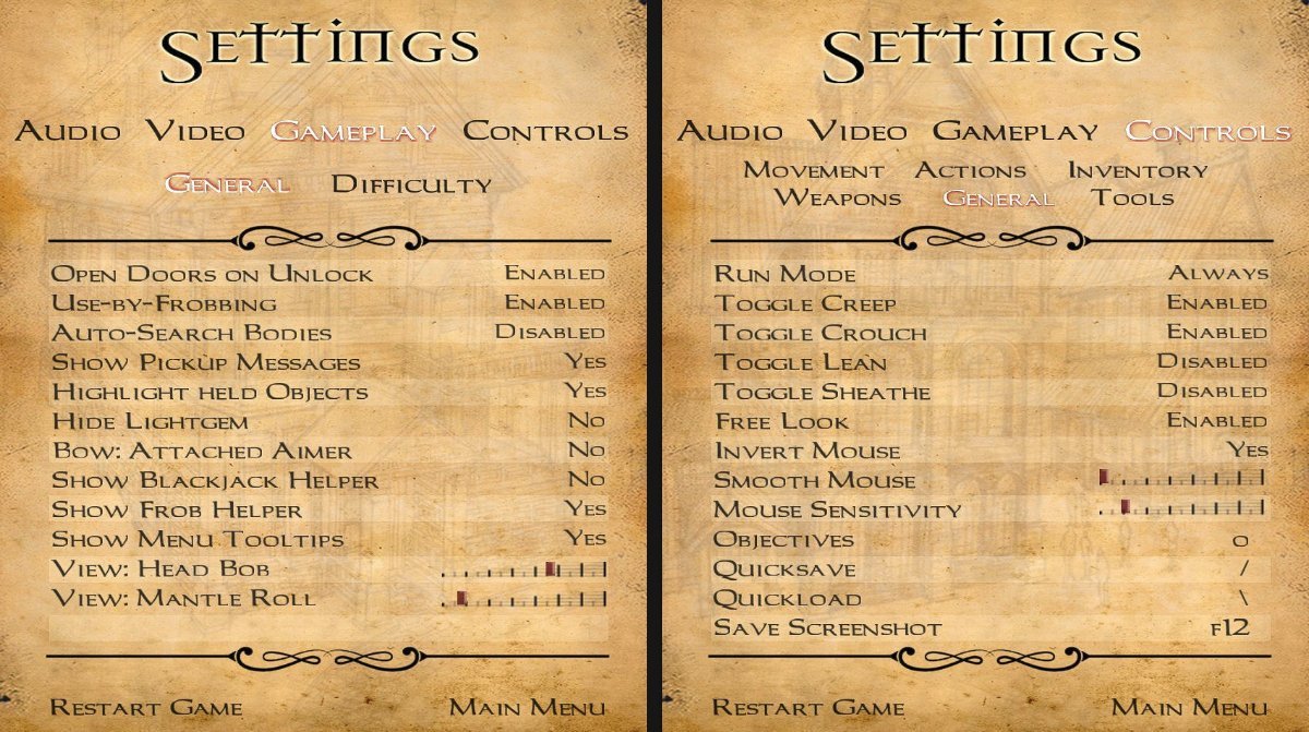
(I apologize for the odd poll question layout. I wasn't able to add five yes-no questions, because polls are limited to three questions.) Hi everyone, I've recently been working on some patches for issues that I've read about from players on the TDM and TTLG forums — and Discord. My goal is to make it as easy as possible for players, especially new players and those who need usability/accessibility options, to find what they need in order to have a better TDM experience. I've already written the GUI and game engine code for these settings, which I've been using in my personal build. The reason for this poll and discussion is to both guide the finalization of my work and collect data to help inform the dev team. Which patches I submit depend on the outcome of this poll, discussion, and what the dev team agrees to accept. Once decided, I can coordinate with the dev team. I've attached screenshots of what the new settings menu would look like if all of the settings are accepted. Below, I have detailed each menu setting, so you can have an easier time understanding each one. Very important to keep in mind: None of these settings change TDM default behavior. They are all opt-in. If you are already happy with the behavior of 2.10, 2.11, etc. and these menu settings are accepted, nothing will change for you. Rename "Always Run" to "Run Mode" with options "None, Always, Toggle" After 2.11 was released, @i30817 requested that "toggle run" be added to the settings menu. Its cvar is already in TDM as "in_toggleRun" (same as Doom 3). I propose renaming the "Always Run" setting to "Run Mode" with options: "None", "Always", and "Toggle". None = in_alwaysRun 0; in_toggleRun 0 Always = in_alwaysRun 1; in_toggleRun 0 Toggle = in_alwaysRun 0; in_toggleRun 1 Show Blackjack Helper @Wellingtoncrab suggested that the new blackjack helper be added to the settings menu. Its cvar was added to 2.11 as "tdm_blackjack_indicate". More info: It's the new blackjack helper added to 2.11. When the game detects that the blackjack can be used for a successful hit or KO, the blackjack will rise slightly. I propose a "Yes/No" setting for this. Slider for "View: Head Bob" @ChronA requested a way to disable head bobbing, because a viewer watching him play was having severe motion sickness. Also, there was a bug in TDM that made setting the head bob in the console not stick after loading a saved game. (Even with 2.11, if a mission overrides the "tdm_player_thief.def" file and sets "pm_bobroll", "pm_bobpitch", "pm_bobup", and other cvars, it will override player preferences.) As far back as 2008, players have had trouble setting head bob. Another one from 2018. At the end of 2022, @Shadowex3 registered just to voice the need for a way to control head bob. I propose that a slider be added to adjust the amount of head bob. This would use a new "pm_headbob_mod" cvar with a value between 0.0 and 1.0 (default 1.0, no change). The "pm_headbob_mod" would be a multiplier for "pm_bobroll", "pm_bobpitch", and "pm_bobup". The advantage to this approach is that missions like Volta 2 and Hazard Pay would not need to adjust their "tdm_player_thief.def" files for head bob to work properly. And, the player can still adjust "pm_bobroll", "pm_bobpitch", and "pm_bobup" as they like. Slider for "View: Mantle Roll" This is similar to head bob for those who are sensitive to motion. Its cvar was added to 2.11 as "pm_mantle_roll_mod". A Thief player on Discord said, "2.11 will have a cvar to tune down the mantling animation at last." I propose that a slider be added for "pm_mantle_roll_mod". Auto-Search Bodies @Zaratul requested the "auto-search bodies" feature from Thief 1 & 2. Its cvar was added to 2.12 dev16783-10307 as "tdm_autosearch_bodies". I did a poll on the a Thief Discord server and roughly 20% of players there use the Thief auto-search bodies feature. I propose a menu setting for this, so that players coming from Thief 1 & 2 can easily find it.

-
How you can help depends a lot on what skills you have. I can Record Video Recording "Let's Play" videos or simple walkthroughs of existing missions and posting them to Youtube is great exposure for the mod (see example .) Be sure to let us know so we can link to them. If you have some editing ability, Video tutorials, where you explain how the mod works, or how to use specific tools, would also be great. Video trailers, showcasing interesting places and features, are also great for publicity. An example is . I can Write Writing reviews for missions are always nice, especially if they include good screenshots. Not only does it give us something to post on other forums, but it makes mappers feel good when their mission gets attention (especially if it's positive). We have a collective thread to post reviews in: http://forums.thedar...s-walkthroughs/ Writing reviews of the mod as a whole, targetted an an audience that doesn't know much about TDM, is also very useful. You could also try offering your services to mappers to create interesting readables, or to proofread for their mission. I can Act and Record Audio We are always on the lookout for good quality audio recordings for vocal sets. If interested, you can pick a few different lines from this script: http://wiki.thedarkm...t:_Average_Jack and send the recordings to Springheel, who then writes a script based on the type of voice you have. I can Translate We could always use translations of our menu/hud into more languages. Also, only a few FMs are aavailable in more than one language, so there is a lot of work there, see the I18N Translator's Guide in the Wiki. I can Model Great! Take a look at the model request thread:http://forums.thedar...-requests-here/ and pick something that interests you. Or just post a, "Hey, anybody want a model?" thread in this forum and I'm sure mappers will get back to you. I can Animate Fantastic. We can always use more good animations. Our current character rigs use a Maya skeleton. PM Springheel for more info. I know C++ Have a look at our coding section in the wiki, pick an issue or feature from the bugtracker of the mod or the leveleditor, download the recent sourcecode release (or better ask for an SVN checkout) and get cracking. Make sure nobody is already working on that specific issue and feel free to ask questions. I can Edit Images We can always use completely new textures and/or improved versions of older textures. How to get started and how to import them into the mod. I can Take Photos Good quality photos of useful textures (medieval-ish building facades, dirt, rocks, wood, etc) are always welcome. The fewer directional shadows and higher resolution, the better. I don't have any skills Even if you can't do any of the above, you can still help out. Talk about TDM in other forums; share your (preferably positive) experiences with other gamers you know. Last, but not least, compliment people when you like their work. Saying "thanks", to a developer or, "I really enjoyed your mission" to a mapper will make their day. -------------------- I'll update this further as more things occur to me.
-

Beta testers wanted: The House of deLisle (by thebigh)
thebigh replied to thebigh's topic in Fan Missions
Awesome! Post is up! https://forums.thedarkmod.com/index.php?/topic/22200-beta-testing-the-house-of-delisle/#comment-487365 Thanks! -

My idea for a reflection / global illumination system
MirceaKitsune replied to MirceaKitsune's topic in The Dark Mod
Got it, and that's great news! I thought the initial plan was to create a new type of map light that captures a cubemap at map start and reflects it. I was thinking that would be better than existing skybox lights, but very inaccurate and unable to capture moving objects in reflections. A global grid based solution will be complex but I do believe worth it in the end. Also am I correct to assume this can tackle both reflections and global illumination? Technically you can project the captured cubemap mirrored in global space for a reflection, as a cube light for GI. Will definitely be amazing if both could be tackled at the same time with a common implementation. -
v 0.14 Switched fake AO & fallback Spec maps to use dot(raw normal map, 0.33) in both ambient & common fs. Switched specular over to use diffuse.rgb color as specular color if no specular.rgb / map texture instead of default static value Normals as fake maps... wasn't happy with how over-dark some things were, eg: the pillars on BikerDude's Training MIssion, when using dots of specular or diffuse as fake maps. So, decided to check out normals instead. I knew normals provide edges to help create the bump-mapping. However, using the normalized & TBN'ed version, I got some surfaces that were pitch black. But, when I dotted the raw normal, I got this... This is a more even-tempered grayscale map for the whole scene. (cut-off seam are from piping the dot product straight through w/o light impacting it). Compared to this... Which was using dot of specular map if it had it, otherwise using dot of diffuse. The over-darkening can possibly be considered a half-arsed materials type of variation on surfaces. But, I'd prefer all surfaces having a more even grayscale to them for a fake AO / specular. Reason being.. I got aggravated with FUEL when vehicles and riders would look over-dark in overcast skies. They looked out of place. Couldn't figure out what the deal was until I piped some materials lighting values directly through, and realized they were applying a default dark gray to some objects lighting.. which over-darked them. When I ripped that out, it was easier to blend things together to look more natural in a scene. (crappy base "materials lighting" FUEL game piped to shaders, which made some things over-dark in overcast skies) So, decided to go with the more equalized fake AO / Specular map. The variations in detail should come from diffuse color, lighting, etc, not from drastic differences in fake maps. (The fake maps are crutches. Shouldn't create drastic differences.) Diffuse for Specular Color TDM shaders did variations on this, mixing in diffuse*0.75+0.25 and such to specular. I pulled that out when I decoupled specular from diffuse, because ideally specular shine amount would be set per-surface / texture. So, dull objects would have a dull shine to let more diffuse color mix in. But, there's static params in the shaders setting amount of specular to use. For shiny metals, it looks ok having white shine come off. But, dull rusty pipes, walls, etc.. not so much. So, if the specular.rgb is missing (which acts as both specular map and specular color), I made the shaders fallback to using the diffuse.rgb as the specular color. Using diffuse as-is, everything looks wet like it's raining or just rained. So, toning it down... Diffuse * 0.1 as fallback spec color. Now it's looking normal again. The color variation is more noticeable in shadows, b/c both specular fallback color and fresnel highlight fallback color rely on diffuse colo rnow. So, the brick is a darker highlight. The bronze metal is more orangish. The white metal door is grayish. Vanity shot... fake AO is darkening seams more now while leaving the "body" of objects to shine through. (IE: the stones on the ground are now having a bit easier time having their highlights on top show up, b/c the normal map as fake AO is more interested in darkening the already dark seams between stones. But, the wet-looking speculars brings up the idea of using a value piped in from the game engine to lerp between dry and wet specular values if environment is raining / damp or not. I'm not sure how level designers flag areas to do rain, or if the value could get piped into the shaders. But, it could create more dynamic environments. EG: walking in the streets in rain, and the streets look wet. Then walk inside some place, and the inside uses dry speculars. The next step on that would be to mix in environmental reflection to make the rain sheen look more rain sheeny. (Because just over-shining speculars tends to make a cheap but tacky wet look.) outval = mix( dryval.rgb, wetval.rgb, vec3(rainamount) ) (EG: The dark rain sheen on the road ahead and the white sheen on the tires is from a cubemap reflection that increases as the game engine's rain value increases, which is used as a lerp factor between dry and wet shading. The FUEL game engine piped in a rain value, and did cubemap reflection for water fresnel reflection. I just put them together in other object shaders to create rain effects on ground, vehicles, etc.) Anyways, shaders are attached. glprogs.stages.interaction.014.zip
-
Still very relevant since a solution to our lack of reflections hasn't been found, this is the type of thread revival I find most welcome. We've been talking about PBR (whether in general or for TDM) and I've been intrigued on whether we can get proper reflections using the specular maps of textures as (reverse) roughness. With the release of 2.11 not far away I've been wanting to hope some sort of solution might make it in time even if that seems unlikely. https://bugs.thedarkmod.com/view.php?id=5239 There's currently an open ticket on implementing light probes that can automatically capture a cubemap from a given position. The technique used here would definitely come in handy for such a thing! An issue with those is mappers would need to add them manually: I'd really prefer an universal solution like SSR so it can work on all FM's without requiring the mapper to enable it, same way SSAO came as an universal improvement. Thus my first idea was rendering a realtime cubemap from the player's POV each frame or every X frames... that would brutalize performance however, especially as it would open all portals around the player to capture a 360* panorama (goodbye view culling). Also it's worth remembering we're dealing with two independent yet interconnected issues here: Ambient lighting and reflection. Ideally a single solution can tackle both, lighting walls with the ambiance of the room as well as showing the reflected view that moves around with the camera. If we were to do it right maybe we could use a smart cubemap to achieve bounce lighting / realtime irradiance... I'm probably going so far off there, still who knows
-
Cauldron v2.0 is finally done! http://forums.thedarkmod.com/topic/19207-fan-mission-volta-ii-cauldron-of-the-gods-by-kingsal-113017-update-v20/
-
The *DOOM3* shaders are ARB2 ('cause of old GeForce support) carmack plan + arb2 - OpenGL / OpenGL: Advanced Coding - Khronos Forums
-
Hi guys, through the "cheats" topic I got the idea, that it would be quite useful, if there were tags for missions (the post was about removing the killing restriction in some missions to suit the prefered play style). I don't know how easy or difficult this is, but with them, it would be quite convenient to pick missions with playstyles, environment, etc one does want to use. This could also be expanded to other mission properties. I remember a discussion about climbable drains, handles on doors, that cannot be picked and other things the map author chooses for himself. That way these things would be clearer and as I said before, it is easier to choose missions with playstyles that suit oneself. What do think?
-
id Studio did a poor job in defining its categorization of variable nomenclature, so in subsequent documentation and discussions there are divergent views (or just slop). In my series, I had to choose something, and went with what I thought would be clearest for the GUI programmer: Properties, which are either Registers (like true variables) Non-registers (like tags) User Variables (also true variables) I see that your view is more along these lines (which perhaps reflects C++ internals?): Flags (like my non-registers) Properties, which are either Built-in (like my registers) Custom (like user Variables) Also, elsewhere, you refer to "registers" as temporaries. I am willing to consider that there could be temporary registers during expression evaluation, but by my interpretation those would be in addition to named property registers. I'm not sure where to go next with this particular aspect, but at least can state it.
-
can somebody fix the mainpage of our site? http://forums.thedarkmod.com/topic/19469-new-layout-error/
-
Experimenting with TDM on Steam Link on Android. see topic http://forums.thedarkmod.com/topic/19432-tdm-on-steam-link-for-android/
-

Why are there no more new fan missions in the missions section ?
AluminumHaste replied to ^^artin's topic in Fan Missions
Keep in mind also that mission size, and complexity have increased dramatically since the beginning. For a lot of veteran mappers, it can take over a year to get a map made and released. The last dozen missions have for the most part been pretty massive, with new textures, sounds, scripts, models etc. We seem to be long past the point of people loading up the tools, and banging out a mission in a few weeks that's very barebones. We still do see some of those, but I noticed in the beta mapper forums and on Discord, that mappers seem to make these maps, but don't release them, and instead use the knowledge gained to make something even better. Could just be bias on my part scrolling through the forums and discord server though. -
Thanks, I can also recommend gog galaxy. The idea of the custom tags is really nice, I'll have to try this out too!
-
Hello, everyone! In this multi-part, comprehensive tutorial I will introduce you to a new light type that has been available in The Dark Mod since version 2.06, what it does, why you would want to use it and how to implement it in your Fan Missions. This tutorial is aimed at the intermediate mapper. Explanations of how to use DarkRadiant, write material files, etc. are outside of its scope. I will, however, aim to be thorough and explain the relevant concepts comprehensively. Let us begin by delineating the sections of the tutorial: Part 1 will walk you through four, distinct ways to add ambient light to a scene, the last way using irradiance environment maps (or IEMs). Lighting a scene with an IEM is considered image-based lighting. Explaining this concept is not in the scope of this tutorial; rather, we will compare and contrast our currently available methods with this new one. If you already understand the benefits IBL confers, you may consider this introductory section superfluous. Part 2 will review the current state of cubemap lights in TDM, brief you on capturing an environment cubemap inside TDM and note limitations you may run into. Three cubemap filtering applications will be introduced and reviewed. Part 3 will go into further detail of the types of inputs and outputs required by each program and give a walkthrough of the simplest way to get an irradiance map working in-game. Part 4 will guide you through two additional, different workflows of how to convert your cubemap to an irradiance map and unstitch it back to the six separate image files that the engine needs. Part 5 will conclude the tutorial with some considerations as to the scalability of the methods hitherto explained and will enumerate some good practices in creating IEMs. Typical scenes will be considered. Essential links and resources will be posted here and a succinct list of the steps and tools needed for each workflow will be summarized, for quick reference. Without further ado, let us begin. Part 1 Imagine the scene. You’ve just made a great environment for your map, you’ve got your geometry exactly how you want it… but there’s a problem. Nobody can appreciate your efforts if they can’t see anything! [Fig. 1] This will be the test scene for the rest of our tutorial — I would tell you to “get acquainted with it” but it’s rather hard to, at the moment. The Dark Mod is a game where the interplay between light and shadow is of great importance. Placing lights is designing gameplay. In this example scene, a corridor with two windows, I have decided to place 3 lights for the player to stealth his way around. Two lights from the windows streak down across the floor and a third, placeholder light for a fixture later to be added, is shining behind me, at one end of the corridor. Strictly speaking, this is sufficient for gameplay in my case. It is plainly obvious, however, that the scene looks bad, incomplete. “Gameplay” lights aside, the rest of the environment is pitch black. This is undesirable for two reasons. It looks wrong. In real life, lights bounce off surfaces and diffuse in all directions. This diffused, omni-directional lighting is called ambient lighting and its emitment can be termed irradiance. You may contrast this with directional lighting radiating from a point, which is called point lighting and its emitment — radiance. One can argue that ambient lighting sells the realism of a scene. Be that as it may, suppose we disregard scary, real-life optics and set concerns of “realism” aside… It’s bad gameplay. Being in darkness is a positive for the player avatar, but looking at darkness is a negative for the player, themselves. They need to differentiate obstacles and objects in the environment to move their avatar. Our current light level makes the scene illegible. The eye strain involved in reading the environment in these light conditions may well give your player a headache, figurative and literal, and greatly distract them from enjoying your level. This tutorial assumes you use DarkRadiant or are at least aware of idtech4’s light types. From my earlier explanation, you can see the parallels between the real life point/ambient light dichotomy and the aptly named “point” and “ambient” light types that you can use in the editor. For further review, you can consult our wiki. Seeing as how there is a danger in confusing the terms here, I will hereafter refer to real life ambient light as “irradiant light”, to differentiate it from the TDM ambient lights, which are our engine’s practical implementation of the optical phenomenon. A similar distinction between “radiant light” and point lights will be made for the same reason. Back to our problem. Knowing, now, that most all your scenes should have irradiant light in addition to radiant light, let’s try (and fail, instructionally) to fix up our gloomy corridor. [Fig. 2] The easiest and ugliest solution: ambient lights. Atdm:ambient_world is a game entity that is basically an ambient light with no falloff, modifiable by the location system. One of the first things we all do when starting a new map is putting an ambient_world in it. In the above image, the darkness problem is solved by raising the ambient light level using ambient_world (or via an info_location entity). Practically every Dark Mod mission solves its darkness problem1 like this. Entirely relying on the global ambient light, however, is far from ideal and I argue that it solves neither of our two, aforementioned problems. Ambient_world provides irradiant light and you may further modulate its color and brightness per location. However, said color and brightness are constant across the entire scene. This is neither realistic, nor does it reduce eye strain. It only makes the scene marginally more legible. Let’s abandon this uniform lighting approach and try a different solution that’s more scene-specific. [Fig. 3] Non-uniform, but has unintended consequences. Our global ambient now down to a negligible level, the next logical approach would be hand-placed ambient lights with falloff, like ambient_biground. Two are placed here, supplementing our window point lights. Combining ambient and point lights may not be standard TDM practice, but multiple idtech4 tutorials extol the virtues of this method. I, myself, have used it in King of Diamonds. For instance, in the Parkins residence, the red room with the fireplace has ambient lights coupled to both the electric light and the fire flame. They color the shadows and enrich the scene, and they get toggled alongside their parent (point) lights, whenever they change state (extinguished/relit). This is markedly better than before, but to be honest anything is, and you may notice some unintended side-effects. The AI I’ve placed in the middle of the ambient light’s volume gets omnidirectionally illuminated far more than any of the walls, by virtue of how light projection in the engine works. Moving the ambient lights’ centers closer to the windows would alleviate this, but would introduce another issue — the wall would get lit on the other side as well. Ambient lights don’t cast shadows, meaning they go through walls. You could solve this by creating custom ambient light projection textures, but at this point we are three ad hocs in and this is getting needlessly complicated. I concede that this method has limited use cases but illuminating big spaces that AI can move through, like our corridor, isn’t one of them. Let’s move on. [Fig. 4] More directional, but looks off. I have personally been using this method in my WIP maps a lot. For development (vs. release), I even recommend it. A point light instead of an ambient light is used here. The texture is either “biground1” or “defaultpointlight” (the latter here). The light does not cast shadows, and its light origin is set at one side of the corridor, illuminating it at an angle. This solves the problem of omnidirectional illumination for props or AI in the middle of the light volume, you can now see that the AI is lit from the back rather than from all sides. In addition, the point light provides that which the ambient one cannot, namely specular and normal interaction, two very important features that help our players read the environment better. This is about as good as you can get but there are still some niggling problems. The scene still looks too monochromatic and dark. From experience, I can tell you that this method looks good in certain scenes, but this is clearly not one of them. Sure, we can use two, non-shadowcasting point lights instead of one, aligned to our windows like in the previous example, we can even artfully combine local and global ambient lights to furnish the scene further, but by this point we will have multiple light entities placed, which is unwieldy to work with and possibly detrimental to performance. Another problem is that a point light’s movable light origin helps combat ambient omnidirectionality, but its projection texture still illuminates things the strongest in the middle of its volume. I have made multiple experiments with editing the Z-projection falloff texture of these lights and the results have all left me unsatisfied. It just does not look right. A final, more intellectual criticism against this method is that this does not, in a technical sense, supply irradiant light. Nothing here is diffuse, this is just radiant light pretending the best it can. [Fig. 5] The irradiance map method provides the best looking solution to imbuing your scene with an ambient glow. This is the corridor lit with irradiance map lights, a new lighting method introduced in The Dark Mod 2.06. Note the subtle gradients on the left wall and the bounced, orange light on the right column. Note the agreeable light on the AI. Comparing the previous methods and this, it is plainly obvious that an irradiance environment map looks the most realistic and defines the environment far better than any of the other solutions. Why exactly does this image look better than the others? You can inform yourself on image-based lighting and the nature of diffuse irradiance, but images speak louder than words. As you can see, the fact of the matter is that the effect, subtle as it may be, substantially improves the realism of the scene, at least compared to the methods previously available to us. Procuring irradiance environment maps for use in lighting your level will hereafter be the chief subject of this tutorial. The next part will review environment cubemap capture in TDM, the makeIrradiance keyword and three external applications that you can use to convert a TDM cubemap into an irradiance map. 1 “ Note that the color buffer is cleared to black: Doom3 world is naturally pitch black since there is no "ambient" light: In order to be visible a surface/polygon must interact. with a light. This explains why Doom3 was so dark ! “ [source] Part 2 Cubemaps are not new to The Dark Mod. The skybox materials in some of our prefabs are cubemaps, some glass and polished tile materials use cubemaps to fake reflections for cheap. Cubemap lights, however, are comparatively new. The wiki page linked earlier describes these two, new light types that were added in TDM 2.05. cubicLight is a shadow-casting light with true spherical falloff. An example of such a light can be found in the core files, “lights/cubic/tdm_lampshade_cubic”. ambientCubicLight is the light type we will be focusing on. Prior to TDM 2.06, it acted as a movable, on-demand reflection dispenser, making surfaces in its radius reflect a pre-set cubemap, much like glass. After 2.06, the old behavior was discarded and ambientCubicLight was converted to accept industry standard irradiance environment maps. Irradiance environment maps (IEMs) are what we want to make, so perhaps the first thing to make clear is that they aren’t really “handmade”. An IEM is the output of a filtering process (convolution) which requires an input in the form of a regular environment cubemap. In other words, if we want to make an IEM, we need a regular cubemap, ideally one depicting our environment — in this case, the corridor. I say a snapshot of the environment is ideal for lighting it because this emulates how irradiant light in the real world works. All radiating surfaces are recorded in our cubemap, our ambient optic array as it were, then blurred, or convoluted, to approximate light scatter and diffusion, then the in-game light “shines” this approximation of irradiant light back to the surfaces. There is a bit of a “chicken and the egg” situation here, if your scene is dark to begin with, wouldn’t you just get a dark irradiance map and accomplish nothing? In the captured cubemap faces in Fig. 6, you may notice that the environment looks different than what I’ve shown so far. I used two ambient lights to brighten up the windows for a better final irradiance result. I’ve “primed the pump”, so to speak. You can ignore this conundrum for the moment, ways to set up your scenes for better results, or priming the pump correctly, will be discussed at the end of the tutorial. Capturing the Environment The wiki has a tutorial on capturing cubemaps by angua, but it is woefully out of date. Let me run you through the process for 2.07 really briefly. To start with, I fly to approx. the center of the corridor with noclip. I then type “envshot t 256” in the console. This outputs six .tga images in the <root>/env folder, simply named “t”, sized 256x256 px and constituting the six sides of a cube and depicting the entire environment. This is how they look in the folder: [Fig. 6] The six cube faces in the folder. Of note here is that I do not need to switch to a 640x480 resolution, neither do I need to rename these files, they can already be used in an ambientCubicLight. Setting Up the Lights For brevity’s sake, I’ll skip explaining material definitions, if you’ve ever added a custom texture to your map, you know how to do this. Suffice it to say, it is much the same with custom lights. In your <root>/materials/my_cool_cubemaps.mtr file, you should have something like this: lights/ambientcube/my_test_IEM_light { ambientCubicLight { forceHighQuality //cameraCubeMap makeIrradiance(env/t) cameraCubeMap env/t colored zeroClamp } } We’ll play with the commented out line in just a bit. Firstly, let’s place the actual light in DarkRadiant. It’s as simple as creating a new light or two and setting them up in much the same way you would a regular ambient light. I select the appropriate light texture from the list, “my_test_IEM_light” in the “ambientcube” subfolder and I leave the light colored pure white. [Fig. 7] The corridor in DR, top view, with the ambient cubic lights highlighted. I can place one that fills the volume or two that stagger the effect somewhat. Remember that these lights still have a spherical falloff. Preference and experimentation will prove what looks best to you. Please note that what the material we defined does is load a cubemap while we established that ambientCubicLights only work with irradiance maps. Let’s see if this causes any problems in-game. I save the map and run it in game to see the results. If I already have TDM running, I type “reloadDecls” in the console to reload my material files and “reloadImages” to reload the .tga images in the /env folder. [Fig. 8] Well this looks completely wrong, big surprise. Wouldn’t you know it, putting a cubemap in the place of an irradiance map doesn’t quite work. Everything in the scene, especially the AI, looks to be bathed in slick oil. Even if a material doesn’t have a specular map, it won’t matter, the ambientCubicLight will produce specular reflections like this. Let’s compare how our cubemap .tga files compares with the IEM .tgas we’ll have by the end of the tutorial: [Fig. 9] t_back.tga is the back face of the environment cubemap, tIEM_back.tga is the back face of the irradiance map derived from it. As you can see, the IEM image looks very different. If I were to use “env/tIEM” instead of “env/t” in the material definition above, I would get the proper result, as seen in the last screenshot of part 1. So it is that we need a properly filtered IEM for our lights to work correctly. Speaking of that mtr def though, let’s not invoke an irradiance map we haven’t learned to convert yet. Let’s try an automatic, in-engine way to convert cubemaps to IEMs, namely the makeIrradiance material keyword. makeIrradiance and Its Limitations Let’s uncomment the sixth line in that definition and comment out the seventh. cameraCubeMap makeIrradiance(env/t) //cameraCubeMap env/t Here is a picture of how a cubemap ran through the makeIrradiance keyword looks like: [Fig. 10] Say ‘Hi’ to our friend in the back, the normalmap test cylinder. It’s a custom texture I’ve made to demonstrate cubemap interactions in a clean way. Hey now, this looks pretty nice! The scene is a bit greener than before, but you may even argue it looks more pleasing to the eyes. Unfortunately, the devil is in the details. Let’s compare the makeIrradiance keyword’s output with the custom made irradiance map setup seen at the end of part 1. [Fig. 11, 12] A closer look at the brick texture reveals that the undesired specular highlighting is still present. The normal map test cylinder confirms that the reason for this is the noisy output of the makeIrradiance keyword. The in-engine conversion is algorithmic, more specifically, it doesn't allow us to directly compare .tga files like we did above. Were we able to, however, I'm sure the makeIrradiance IEM would look grainy and rough compared to the smooth gradient of the IEM you’ll have by the end of this tutorial. The makeIrradiance keyword is good for quick testing but it won’t allow you fine control over your irradiance map. If we want the light to look proper, we need a dedicated cubemap filtering software. A Review of Cubemap Filtering Software Here I’ll introduce three programs you can produce an irradiance map with. In the coming parts, I will present you with a guide for working with each one of them. I should also note that installing all of these is trivial, so I’ll skip that instructional step when describing their workflows. I will not relay you any ad copy, as you can already read it on these programs’ websites. I’ll just list the advantages and disadvantages that concern us. Lys https://www.knaldtech.com/lys/ Advantages: Good UI, rich image manipulation options, working radiance/specular map filtering with multiple convolution algorithms. Disadvantages: $50 price tag, limited import/export options, only available on Windows 64-bit systems. cmftStudio https://github.com/dariomanesku/cmftStudio Advantages: Available on Windows, OSX and Linux, free, open source software, command line interface available. Disadvantages: Somewhat confusing UI, limited import options, missing features (radiance/specular map filtering is broken, fullscreen doesn’t work), 32-bit binaries need to be built from source (I will provide a 32-bit Windows executable at the end of the tutorial). Modified CubeMapGen https://seblagarde.wordpress.com/2012/06/10/amd-cubemapgen-for-physically-based-rendering/ Advantages: Free software, quickest to work with (clarified later). Disadvantages: Bad UI, only Windows binaries available, subpar IEM export due to bad image adjustment options. Let’s take a break at this point and come back to these programs in part 3. A lot of caveats need to be expounded on as to which of these three is the “best” software for making an irradiance map for our purposes. Neither of these programs has a discreet workflow; rather, the workflow will include or exclude certain additional programs and steps depending on which app you choose to work with. It will dovetail and be similar in all cases. Part 3 The aim of this tutorial is twofold. First, it aims to provide the most hands-free and time-efficient method of converting an envshot, environment cubemap to an IEM and getting it working in-game. The second is using as few applications as possible and keeping them all free software that is available for download, much like TDM itself. The tutorial was originally going to only cover IEM production through Lys, as that was the app I used to test the whole process with. I soon realized that it would be inconsiderate of me to suggest you buy a fifty dollar product for a single step in a process that adds comparatively little to the value of a FM, if we’re being honest (if you asked me, the community would benefit far more from a level design tutorial than a technical one like this, but hey, maybe later, I’m filling a niche right now that nobody else has filled). This led me to seek out open-source alternatives to Lys, such as Cubemapgen, which I knew of and cmftStudio, which I did not. I will preempt my own explanations and tell you right away that, in my opinion, cmftStudio is the program you should use for IEM creation. This comes with one big caveat, however, which I’m about to get into. Six Faces on a Cross and The Photoshop Problem Let’s review. Taking an envshot in-game gives you six separate images that are game-ready. Meaning, you get six, split cubemap faces as an output, you need six, split irradiance map faces as an input. This is a problem, because neither Lys nor cmftStudio accept a sequence of images as such. They need to be stitched together in a cube cross, a single image of the unwrapped cube, like this: [Fig. 13] From Lys. Our cubemap has been stitched into a cross and the “Debug Cube Map Face Position” option has been checked, showing the orientations of each face. In Lys only panoramas, sphere maps and cube maps can be loaded into the program. The first two do not concern us, the third specifically refers to a single image file. Therefore, to import a TDM envshot into Lys you need to stitch your cubemap into a cross. Furthermore, Lys’ export also outputs a cubemap cross, therefore you also need to unstitch the cubemap into its faces afterwards if you want to use it in TDM. In cmftStudio you can import single map faces! Well… no, you can’t. The readme on GitHub boasts “Input and output types: cubemap, cube cross, latlong, face list, horizontal and vertical strip.” but this is false. The UI will not allow you to select multiple files on import, rendering the “face list” input type impossible.2 Therefore, to import a TDM envshot into cmftStudio you need to stitch your cubemap into a cross. Fortunately, the “face list” export type does work! Therefore, you don’t need to unstitch the cubemap manually, cmftStudio will export individual faces for you. In both of these cases, then, you need a cubemap cross. For this tutorial I will use Adobe Photoshop, a commercial piece of software, to stitch our faces into a cubemap in an automated fashion (using Photoshop’s Actions). This is the big caveat to using cmftStudio, even if you do not want to buy Lys, PS is still a prerequisite for working with both programs. There are, of course, open source alternatives to Photoshop, such as GIMP, but it is specifically Photoshop’s Action functionality that will power these workflows. GIMP has its own Actions in the form of Macros, but they are written with python. GIMP is not a software suite that I use, neither is python a language I am proficient with. Out of deference for those who don’t have, or like working with, Photoshop, I will later go through the steps I take inside the image editor in some detail, in order for the studious reader to reconstruct them, if they so desire, in their image editing software of choice. At any rate, and at the risk of sounding a little presumptuous, I take it that, as creative types, most of you already have Photoshop on your computers. 2 An asterisk regarding the “impossibility” of this. cmftStudio is a GUI for cmft, a command line interface that does the same stuff but inside a command prompt. I need to stress that I am certain multiple faces can be inputted in the command line, but messing with unwieldy prompts or writing batch files is neither time-saving nor user-friendly. This tutorial is aimed at the average mapper, but a coder might find the versatility offered in cmft interesting. The Cubemapgen Workflow You will have noticed that I purposefully omitted Cubemapgen from the previous discussion. This is because working with Cubemapgen, wonderfully, does not need Photoshop to be involved! Cubemapgen both accepts individual cubemap faces as input and exports individual irradiance map faces as output. Why, then, did I even waste your time with all the talk of Lys, cmftStudio and Photoshop? Well, woefully, Cubemapgen’s irradiance maps look poor at worst and inconsistent at best. Comparing IEMs exported from Lys and cmftStudio, you will see that both look practically the same, which is good! An IEM exported from Cubemapgen, by default, is far too desaturated and the confusing UI does not help in bringing it to parity with the other two programs. If you work solely with Cubemapgen, you won’t even know what ‘parity’ is, since you won’t have a standard to compare to. [Fig. 14] A comparison between the same irradiance map face, exported with the different apps at their respective, default settings. Brightened and enlarged for legibility. This may not bother you and I concede that it is a small price to pay for those not interested in working with Photoshop. The Cubemapgen workflow is so easy to describe that I will in fact do just that, now. After I do so, however, I will argue that it flies in the face of one of the aims of this tutorial, namely: efficiency. Step 1: Load the cubemap faces into Cubemapgen. Returning to specifics, you will remember that we have, at the moment, six .tga cubemap faces in a folder that we want to convert to six irradiance map faces. With Cubemapgen open, direct your attention to these buttons: [Fig. 15] You can load a cubemap face by pressing the corresponding button or using the hotkey ‘F’. To ensure the image faces the correct way, you must load it in the corresponding “slot”, from the Select Cubemap Face dropdown menu above, or by pressing the 1-6 number keys on your keyboard. Here is a helpful list: X+ Face <1> corresponds to *_right X- Face <2> corresponds to *_left Y+ Face <3> corresponds to *_up Y- Face <4> corresponds to *_down Z+ Face <5> corresponds to *_forward Z- Face <6> corresponds to *_back ...with the asterisk representing the name of your cubemap. With enough practice, you can get quite proficient in loading cubemap faces using keyboard shortcuts. Note that the ‘Skybox’ option in the blue panel is checked, I recommend you use it. Step 2: Generate the Irradiance Map [Fig. 16] The corridor environment cubemap loaded in and filtered to an irradiance map. The options on the right are my attempt to get the IEM to look right, though they are by no means prescriptive. Generating an IEM with Modified CubeMapGen 1.66 is as easy as checking the ‘Irradiance cubemap’ checkbox and hitting ‘Filter Cubemap’ in the red panel. There are numerous other options there, but most will have no effect with the checkbox on. For more information, consult the Sébastien Lagarde blog post that you got the app from. I leave it to you to experiment with the input and output gamma sliders, you really have no set standard on how your irradiance map is supposed to look, so unfortunately you’ll have to eyeball it and rely on trial and error. Two things are important to note. The ‘Output Cube Size’ box in the red panel is the resolution that you want your IEM to export to. In the yellow panel, make sure you set the output as RGB rather than RGBA! We don’t need alpha channels in our images. Step 3: Export Irradiance Map Faces Back in the green panel, click the ‘Save CubeMap to Images’ button. Save the images as .tga with a descriptive name. [Fig. 17] The exported irradiance map faces in the folder. These files still need to be renamed with appropriate suffixes in order to constitute a readable cubemap for the engine. The nomenclature is the same as the table above: “c00” is the X+ Face, to be renamed “right”, “c01” is the X- Face and so on. Right left, up down, forward and back. That’s the order! This is all there is to this workflow. A “cameraCubeMap env/testshot” in the light material will give us a result that will look, at the very least, better than the inbuilt makeIrradiance material keyword. [Fig. 17] The map ended up being a little bright. Feel free to open Fig. 4 and this in seperate tabs and compare the Lys/cmft export with the cubemapgen one. A Review of the Workflow Time for the promised criticism to this workflow. I already stated my distaste for the lack of a standardised set of filtering values with this method. The lack of any kind of preset system for saving the values you like makes working with Cubemapgen even more slipshod. Additionally, in part 2, I said that Cubemapgen is the fastest to work with, but this needs to be qualified. What we just did was convert one cubemap to an irradiance map, but a typical game level ought to use more than a single IEM. Premeditation and capturing fake, “generic” environment cubemaps (e.g. setting up a “blue light on the right, orange on the left” room or a “bright skylight above, brown floor” room, then capturing them with envshot) might allow for some judicious reuse and keep your distinct IEM light definition count down to single digits, but you can only go so far with that. I am not arguing here for an ambient cubic light in every scene either, certainly only those that you deem need the extra attention, or those for which the regular lighting methods enumerated in Part 1 do not quite work. I do tentatively assume, though, that for an average level you would use between one and two dozen distinct IEMs. Keep in mind that commercial games, with their automated probe systems for capturing environment shots, use many, many more than that. With about 20 cubemaps to be converted and 6 faces each to load into Cubemapgen, you’ll be going through the same motions 120 whole times (saving and renaming not included). If you decide to do this in one sitting (and you should, as Cubemapgen, to reiterate, does not keep settings between sessions), you are in for a very tedious process that, while effective, is not very efficient. The simple fact is that loading six things one by one is just slower than loading a single thing once! The “single thing” I’m referring to is, of course, the single, stitched cubemap cross texture. In the next part, I will go into detail regarding how to make a cubemap cross in Photoshop in preparation for cmftStudio and Lys. It will initially seem a far more time-consuming process to you than the Cubemapgen workflow, but through the magic of automation and the Actions feature, you will be able to accomplish the cubemap stitch process in as little as a drag-and-drop into PS and a single click. The best thing is that after we go through the steps, you won’t have to recreate them yourself, as I will provide you with a custom Actions .atn file and save you the effort. I advise you not to skip the explanations, however. The keen-eyed among you may have noticed that you can also load a cube cross in Cubemapgen. If you want to use both Cubemapgen and Photoshop together to automate your Cubemapgen workflow, be aware that Cubemap gen takes crosses that have a different orientation than the ones Lys and cmftStudio use. My macros (actions) are designed for the latter, so if you want to adjust them for Cubemapgen you would do well to study my steps and modify them appropriately. For the moment, you’ve been given the barebones essentials needed to capture an envshot, convert it to an irradiance map and put it in your level at an appropriate location, all without needing a single piece of proprietary software. You can stop here and start cranking out irradiance maps to your heart’s content, but if you’re in the mood for some more serious automation, consider the next section.
-
Thief4 trainer with NOCLIP mode - http://forums.thedarkmod.com/topic/16001-thief-4-tweaks-fixes/page-7?do=findComment&comment=420152
-
YOU TAFFERS! Happy new year! Deadeye is a small/tiny assassination mission recommended for TDM newcomers and veterans alike. Briefing: Download link: https://drive.google.com/file/d/1JWslTAC3Ai9kkl1VCvJb14ZlVxWMmkUj/view?usp=sharing Enjoy! EDIT: I promised to someone to write something about the design of the map. This is in spoiler tags below. Possibly useful to new mappers or players interested in developer commentary.
- 27 replies
-
- 17
-

-
Bump maps not blending in vertex blended materials
nbohr1more replied to grodenglaive's topic in TDM Tech Support
Seems to confirm: https://bugs.thedarkmod.com/view.php?id=5718 does it happen in the latest dev build: https://forums.thedarkmod.com/index.php?/topic/20824-public-access-to-development-versions/ -
Voice actors needed - details in beta topic: http://forums.thedarkmod.com/topic/19360-proofreading-and-voice-actors-needed-for-fm/?p=419500
-
I just read@motorsep Discovered that you are able to create a brush, then select it and right click "create light". Now you have a light that ha the radius of the former brush. Just read it on discord and thought it may be of use for some people in the forums here too.
-

RPS Article on Thief genre from perspective of original TTLG dev
New Horizon replied to Shadow's topic in Off-Topic
TTLG? That's Through the Looking Glass Forums. A looking glass fan community. Has been around for a long, long time. https://www.ttlg.com/forums/ -
Yes, if you have static reflection. Did reflection got into C++20 already? Yeah, it is a lot of fun, but only if you really looking for this kind of fun
-

TDM Beta Release schedule confusion and frustrations
Dragofer replied to Daft Mugi's topic in The Dark Mod
I think the reason the dev forums exist is to provide a place where the implementation of features can be discussed without getting mixed up with other debates when someone believes what the devs are doing is wrong. We often post public discussion threads for features with subjective elements like the frob outline, because community feedback is very important. But there will always be vocal defenders with strong views for or against certain features, or how exactly it should be implemented in their opinion. At some point a decision has to be made and be carried through, which is what the dev forums are for. Almost all of the threads are very technical, basically explaining and discussing recent or potential code changes with other devs. Its hard to say. Its a hobby the devs do in their spare time, so people come and go when they're in the mood and when they have the time. The team page is mostly accurate except for some relatively newer additions like myself. -
I just found this thread on ttlg listing Immersive Sims: https://www.ttlg.com/forums/showthread.php?t=151176
-
https://github.com/HansKristian-Work/vkd3d-proton/tags <- directx 12 wrapper for dxvk https://github.com/doitsujin/dxvk/tags <- directx to vulkan wrappers D3D 9 to 11 eg. dxvk if you want to try it with horizon zero dawn you need to copy out dxcompiler.dll from Tools\ShaderCompiler\PC\1.0.2595\x64 and bink2w64.dll from Tools\bin and place them next to HorizonZeroDawn.exe. then copy over dxgi.dll from dxvk and d3d12.dll from vkd3d and place them next to it to. now fire up the game and let the shaders recompile -> profit.